Method and device for antenna calibration

a technology for antennas and devices, applied in antenna radiation diagrams, instruments, antennas, etc., can solve the problems of affecting the influence of reflection, affecting the transmission of signals through antenna elements, and affecting the effect of the arrangemen

Inactive Publication Date: 2000-10-03
TELEFON AB LM ERICSSON (PUBL)
View PDF12 Cites 84 Cited by
  • Summary
  • Abstract
  • Description
  • Claims
  • Application Information

AI Technical Summary

Problems solved by technology

The signals transmitted through the antenna elements interfere with each other.
In, for example, an airplane radar such an arrangement is of course impossible if it is to be possible to calibrate during operation.
It is generally impossible to predict the influence of these reflections and this type of calibration is therefore not suitable, for example, for an airplane radar.
The disadvantage of this solution is the high complexity implied by the distribution network, in particular in

Method used


Image

  • Method and device for antenna calibration
  • Method and device for antenna calibration
  • Method and device for antenna calibration

Examples


Embodiment Construction

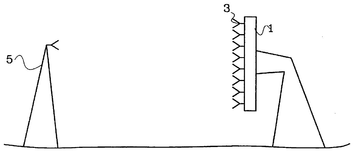
FIG. 1 shows how calibration of an electrically controlled antenna 1 can be carried out according to prior art. A test antenna 5 is placed at a remote field distance from the electrically controlled antenna 1. The position of the test antenna 5 relative to the electrically controlled antenna 1 is accurately measured. The test antenna 5 and the electrically controlled antenna 1 are positioned in such a way as to minimize the reflections occurring from the surroundings.

At calibration during reception a test signal is transmitted from the test antenna 5 and received through the electrically controlled antenna 1. The way in which the test antenna 5 is arranged in FIG. 1 makes it possible to determine the phase and the amplitude of the signals inserted into the radiation elements 3 of the electrically controlled antenna 1 relatively accurately. By measuring the phase and the amplitude of the signal received through the electrically controlled antenna 1, it is thus possible to obtain info...


PUM


Abstract

The present invention relates to the problem of calibrating an antenna system (23) comprising an electrically controlled antenna (25) using a test antenna (45) arranged near the electrically controlled antenna, with the possibility of calibrating during operation, when disturbing reflections or other unknown signal influences are present when signals are transmitted between the test antenna and the electrically controlled antenna or between the electrically controlled antenna and the test antenna. The electrically controlled antenna comprises a number of modules (27-(1-N)) having means (91-(1-N)) for controlling the complex amplification of the modules. Each module is arranged with a commandable reference mode at reception and/or transmission. The antenna system is calibrated for reception and transmission, respectively, by transmitting test signals between the test antenna and the electrically controlled antenna and/or by transmitting test signals between the electrically controlled antenna and the test antenna, the effect of the unknown signal influence being eliminated by utilization of the reference modes at reception and/or transmission.

Description

The present invention is related to devices and methods for antenna calibration. In particular the invention is related to calibration of antenna systems comprising electrically controlled antennas.DESCRIPTION OF RELATED ARTMany technical applications comprise some form of antenna function, in which signals are to be received or transmitted through air. Examples of such applications are radios, television sets, mobile telephony systems and radar systems.The demand for directional function in an antenna varies with the application. A radio is to be able to receive signals from different radio stations independently of where it has been placed, and the antenna should therefore preferably be equally sensitive in all directions in the horizontal plane. A television set, on the other hand, should only be sensitive to signals coming from the nearest television mast. The antenna of a television set should therefore be arranged in such a way that it is particularly sensitive to signals comi...

Claims


Application Information

Patent Timeline
IPC IPC(8): H01Q3/26G01R29/10
CPCG01S7/4026H01Q3/267G01S7/4052G01S2007/406G01S2013/0245G01S7/406
Inventor ERHAGE, LARS INGEMAR
Owner TELEFON AB LM ERICSSON (PUBL)
Why Eureka
Try Eureka