Dual polarized slotted array antenna

a slotted array, dual-polar technology, applied in the direction of slot antennas, antennas, linear waveguide fed arrays, etc., can solve the problems that the addition of cavity sections and output slots have little effect on the overall array thickness or weight, and achieve the effect of efficiently passing electromagnetic signals

Inactive Publication Date: 2000-10-03
EMS TECHNOLOGIES
View PDF15 Cites 96 Cited by
  • Summary
  • Abstract
  • Description
  • Claims
  • Application Information

AI Technical Summary

Benefits of technology

Each cavity section of the radiator plate is associated with one of the output slots and comprises a first opening and a second opening. The first opening is positioned adjacent to one of the input slots to allow the cavity section to accept the electromagnetic signals having the first polarization state from the input slot. The second opening is positioned adjacent to one of the output slots to allow the cavity section to pass the electromagnetic signals having the second polarization state to the output slot. The cavity section can be viewed as a transitional section of transmission line, located between the input slot and the output slot, for rotating the polarization of electromagnetic signals from the first polarization state to the second polarization state, and for passing the electromagnetic signals efficiently from the input slot to the output slot. Each output slot receives electromagnetic signals having the second polarization state from the cavity section, and responds by radiating electromagnetic signals of the second polarization state to free space. To achieve a change in the polarizationof the electromagnetic signals, the output slots are typically rotated in position relative to the input slots.
For one aspect of the present invention, a 45.degree. slant left polarization slot array can be interlaced with a 45.degree. slant right polarization slot array within a common antenna structure to provide the capability of transmitting and receiving simultaneous dual orthogonal linear polarization states. This can be accomplished by alternating the placement of side-by-side waveguide assemblies, the first waveguide assembly comprising waveguide slot radiators for communicating electromagnetic signals of a selected polarization state (e.g., 45.degree. slant left) and the second waveguide assembly comprising waveguide slot radiators for communicating electromagnetic signals of another selected polarization state (e.g., 45.degree. slant right). Consequently, the present invention can support the implementation of a slotted array antenna comprising interlaced slotted arrays within a common antenna structure for communicating signals having simultaneous dual orthogonal polarization states. The signals exhibiting dual orthogonal polarization states can have the same frequency range or different frequency bands.

Problems solved by technology

Consequently, the additional cavity section and the output slot have little effect on the overall array thickness or weight of a slotted array antenna employing this waveguide slot radiator design.

Method used


Image

  • Dual polarized slotted array antenna
  • Dual polarized slotted array antenna
  • Dual polarized slotted array antenna

Examples


Embodiment Construction

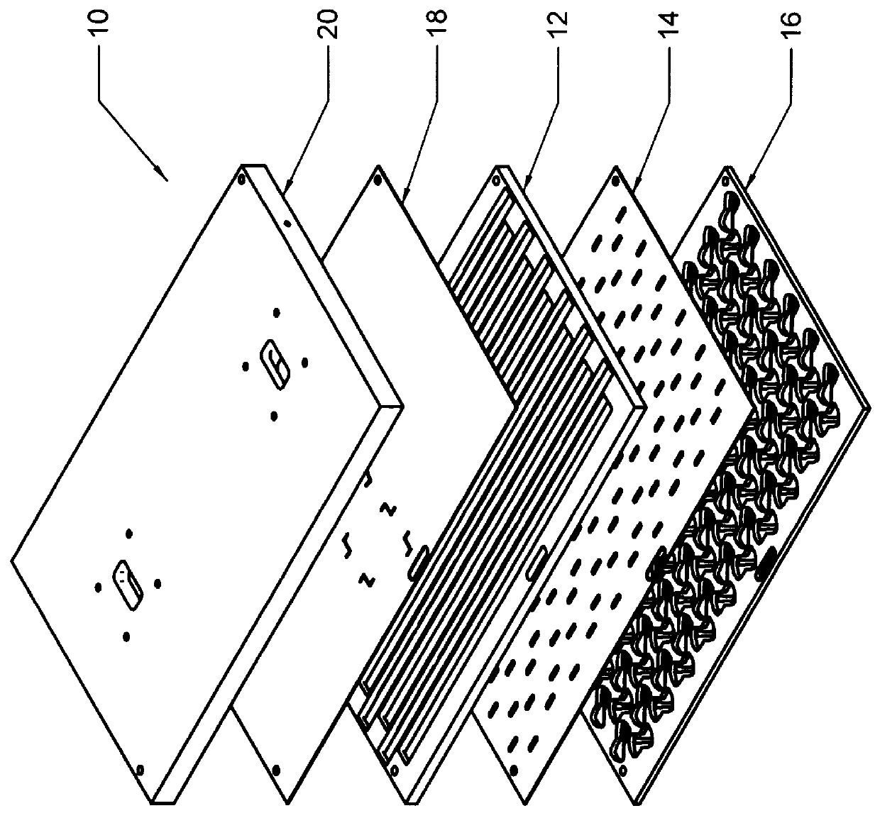
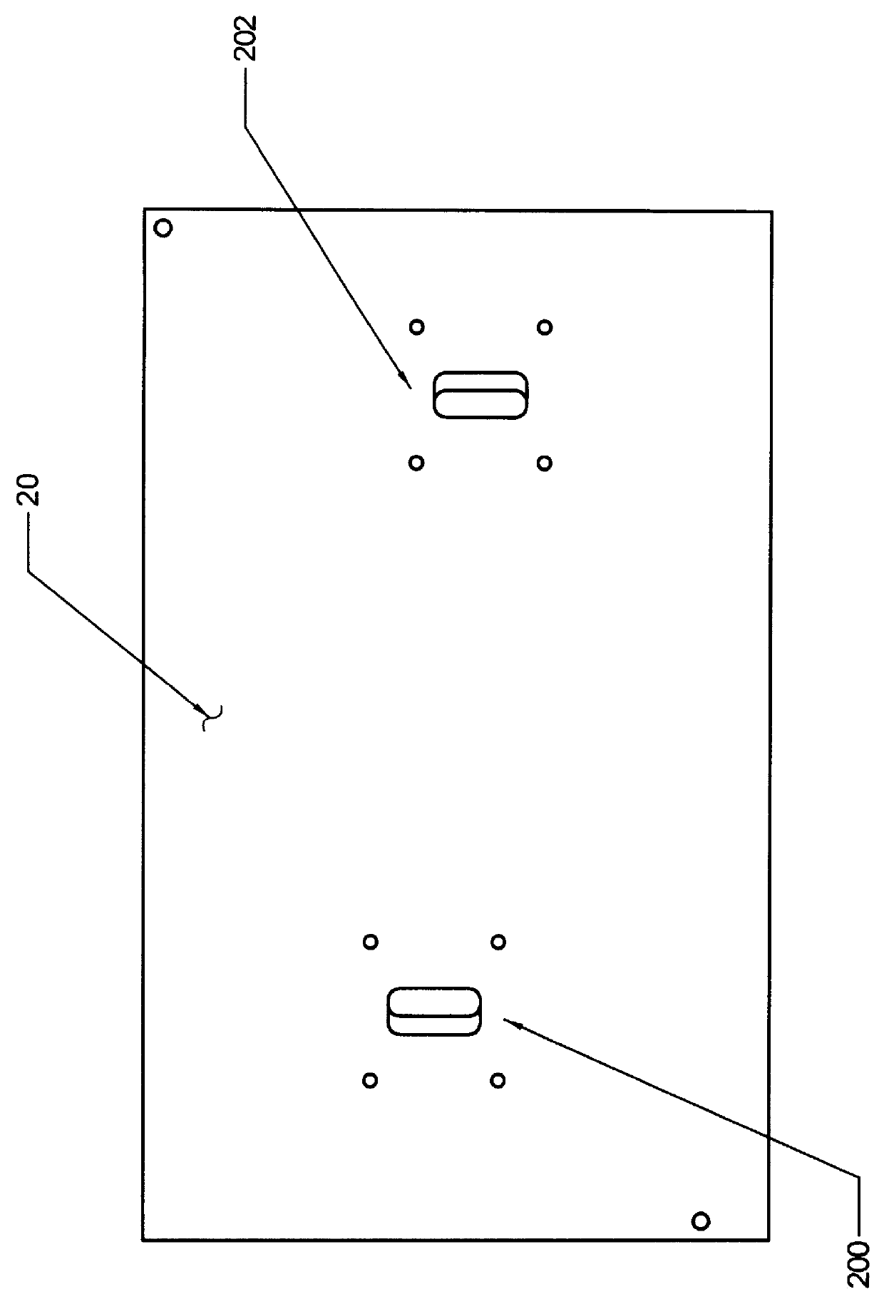
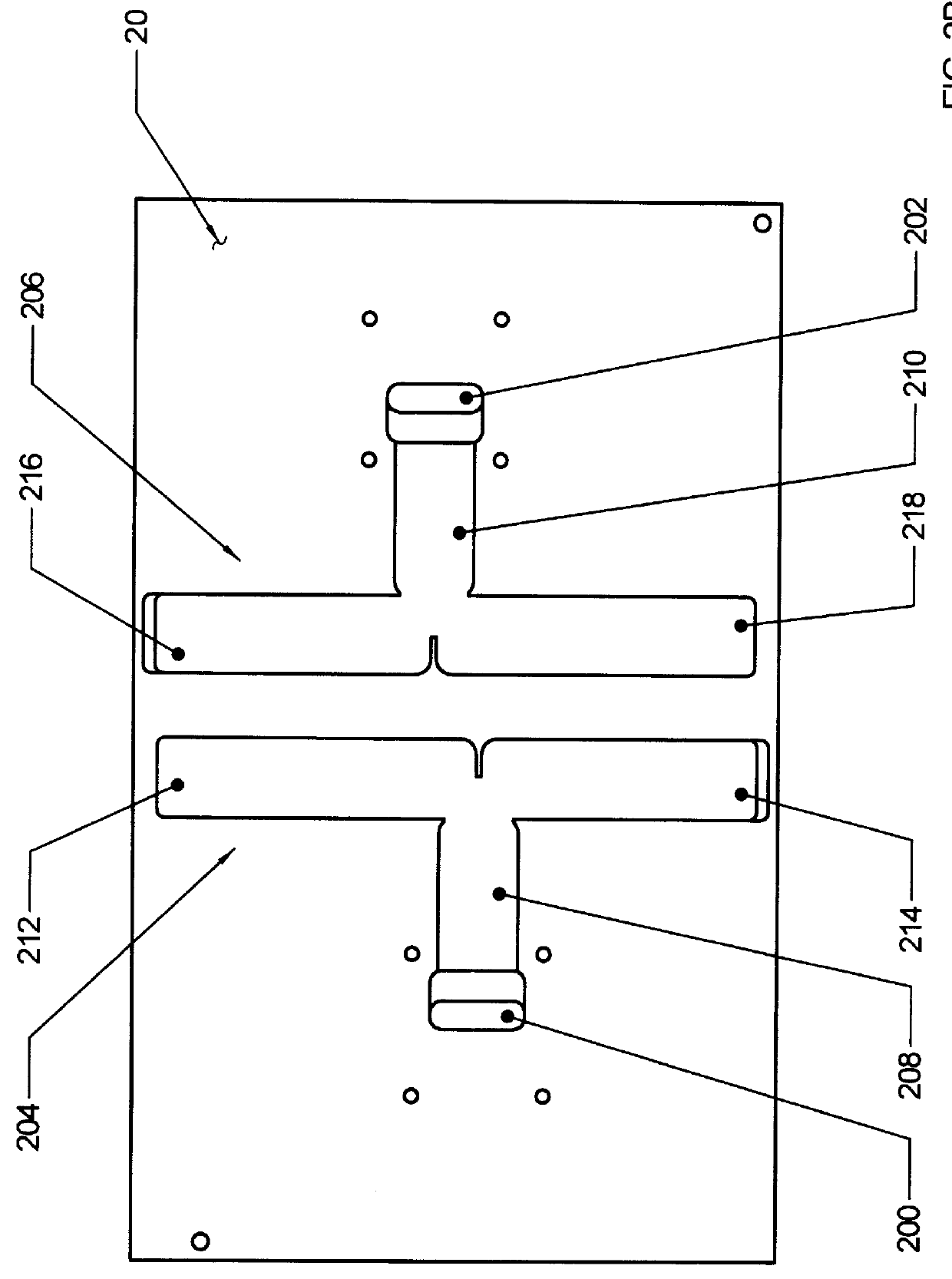
The present invention provides a ridged waveguide-implemented antenna including a planar array of improved waveguide slot radiators for communicating electromagnetic signals exhibiting simultaneous dual polarization states. The antenna can be implemented in a single antenna structure by interleaving alternate waveguide assemblies, each supporting one of a pair of orthogonal polarization states. For example, an array of waveguide assemblies having 45.degree. slant left waveguide slot radiators can be interlaced with an array of waveguide assemblies having 45.degree. slant right waveguide slot radiators within a common antenna structure to support the transmission and reception of electromagnetic signals having simultaneous dual orthogonal linear polarization states. Each waveguide slot radiator is implemented by a transitional cavity section positioned between an input slot and an output slot. The output slot can be rotated in position relative to the input slot to change the polariz...


PUM


Abstract

A waveguide-implemented antenna comprising a planar array of waveguide slot radiators for communicating electromagnetic signals exhibiting simultaneous dual polarization states. The antenna can consist of parallel ridged waveguides having rectangular or "T"-shaped ridged cross sections. The ridged walls of each parallel ridged waveguide contain a linear array of input slots for receiving (transmitting) electromagnetic signals having a first polarization state from (to) the parallel ridged waveguides and for transmitting (receiving) those signals into (from) a corresponding array of cavity sections. The cavity sections comprise a short section of uniform waveguide with a thickness of much less than a wavelength in the propagation direction. The cavity sections feed to output slots which are rotated relative to the input slots; such that the output slots exhibit a second polarization state, which they radiate (receive) to (from) free space. By interlacing parallel ridged waveguides with alternating +45 degree and -45 degree rotations of the output slots, two independent antennas are formed exhibiting simultaneous dual polarizations. Because the input slots are located in the ridge wall of the parallel ridged waveguides, the parallel ridged waveguides can be fed from their broad wall side. Feeding the parallel ridged waveguides from their broad wall side eliminates a need for a complex feed network.

Description

FIELD OF THE INVENTIONThe invention is generally directed to a slotted array antenna for communicating electromagnetic signals and, more particularly described, is a ridged waveguide-implemented planar array antenna using improved ridged waveguide slot radiators to communicate electromagnetic signals with simultaneous dual polarization states.BACKGROUND OF THE INVENTIONSlotted array antennas commonly use a waveguide distribution network for distributing RF energy to and from an array of slots placed along the broad wall of a waveguide channel. These waveguide-implemented antennas can be used for communication applications requiring space-limited mountings, such as in aircraft installations. In satellite communications applications, however, it is often a requirement that the antenna be capable of transmission and reception of signals having two different characteristic polarization states. This requirement can prove to be a significant obstacle to designing a space-limited slotted a...

Claims


Application Information

Patent Timeline
Patent Type & Authority Patents(United States)
IPC IPC(8): H01Q13/10H01Q21/00H01Q21/06
CPCH01Q13/10H01Q21/064H01Q21/005
Inventor GULER, MICHAEL G.
Owner EMS TECHNOLOGIES
Why Eureka
Try Eureka