

Printing system
a printing system and printing technology, applied in the direction of digital output to print units, visual presentation using printers, instruments, etc., can solve the problems of long print processing time and ineffective registration of characters across a plurality of documents
- Summary
- Abstract
- Description
- Claims
- Application Information
AI Technical Summary
Benefits of technology
Problems solved by technology
Method used
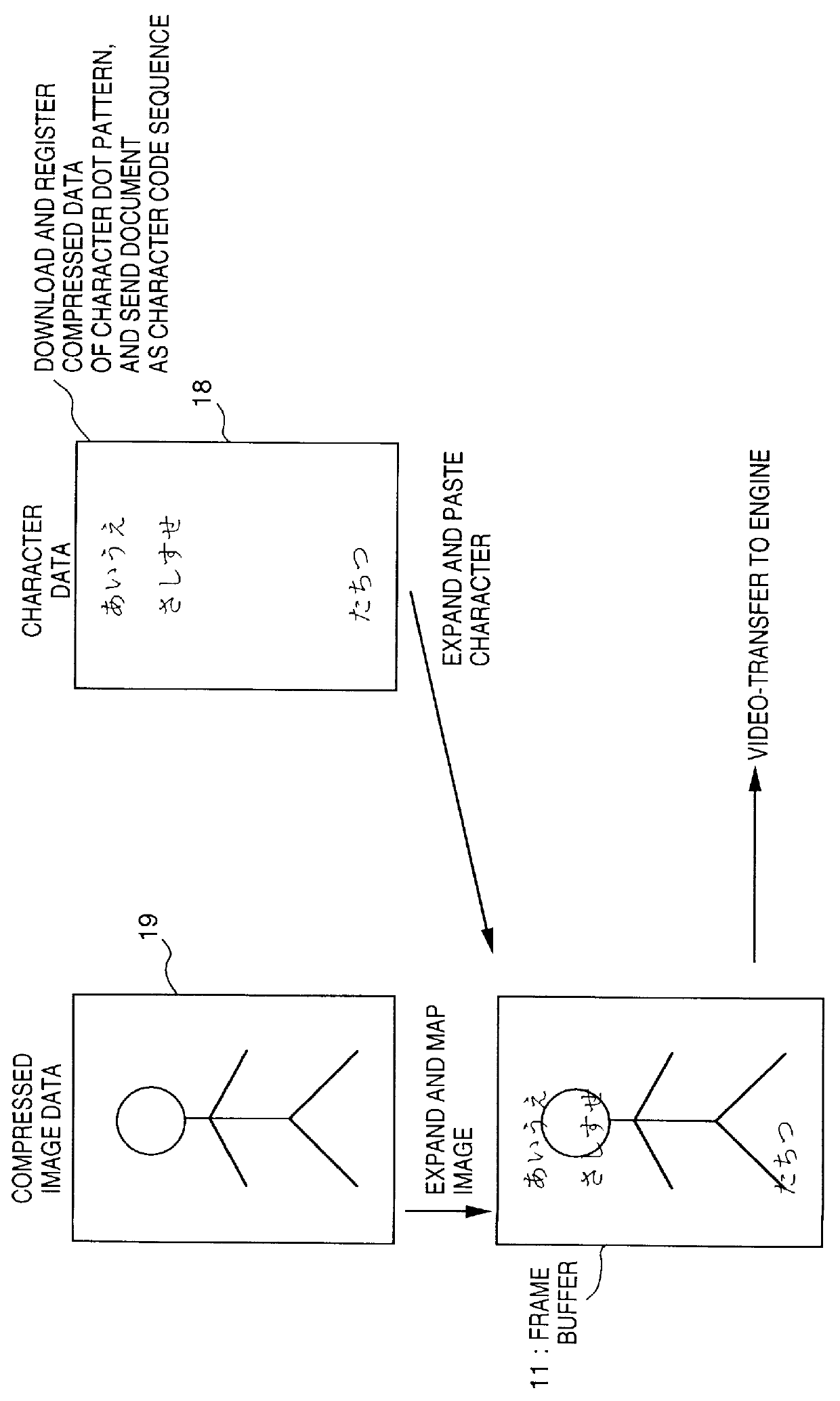
Image

Examples
second embodiment
[Second Embodiment]
A printing system of the second embodiment will be described below with reference to the accompanying drawings.
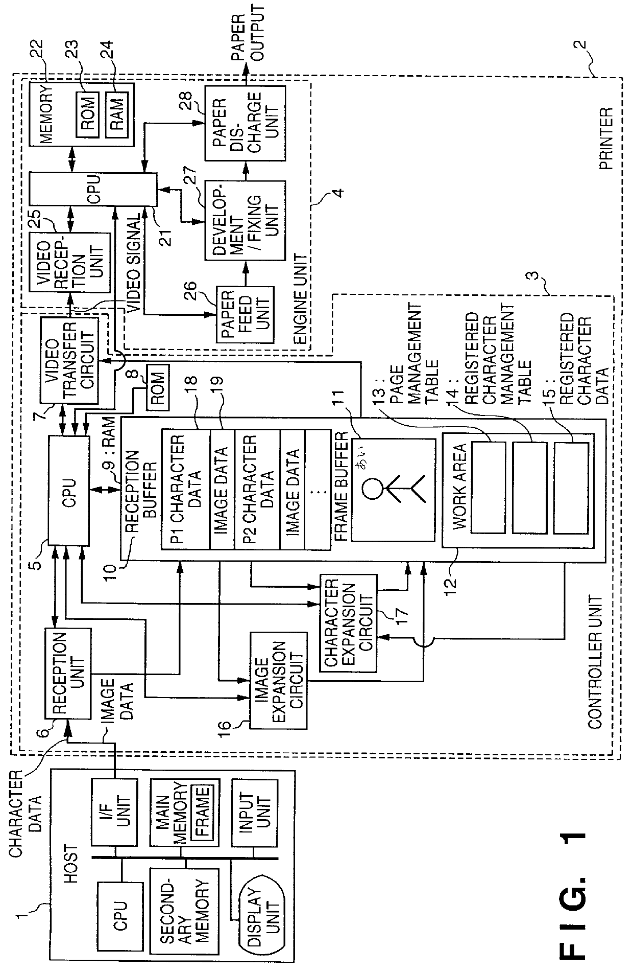
In the first embodiment, character and image data are mapped onto the frame buffer 11 on the RAM 9, and are then transferred to the engine unit 4 as a video signal. However, in the second embodiment, unlike in the first embodiment, character and image data are alternately mapped onto two band memories on the RAM 9, and are transferred to the engine unit 4 as a video signal.
FIG. 18 is a block diagram for explaining the arrangement of the entire system. Since most of components are the same as those described in FIG. 1, only differences will be explained below.
Bands A 71 and B 72 are allocated as two band memories on the RAM 9 in place of the frame buffer 11, and an image expansion / video transfer circuit 73 replaces the video transfer circuit 7. The image expansion / video transfer circuit 73 alternately converts memory images on the bands A 71 and B 72 into ...
third embodiment
[Third Embodiment]
The third embodiment will be described below with reference to the accompanying drawings.
In the second embodiment, one page is equally divided into 16 bands. However, in the third embodiment, the number of bands and the height of each band can be variably set, and when image data include repetitive image patterns in units of bands, the driver sends a repetition command of a band to the printer, thereby reducing the quantity of image data to be transferred.
However, since the constituting elements, program operations, and the like of this embodiment are nearly the same as those in the second embodiment, the differences will be mainly described below.
Since the block arrangement is the same as that in FIG. 18 of the second embodiment, a detailed description thereof will be omitted. In the third embodiment, the band height is arbitrarily set within the band height of the band A 71 or B 72 allocated on the RAM 9 in FIG. 18.
FIG. 34 is an explanatory view of the principle ...
fourth embodiment
[Fourth Embodiment]
The fourth embodiment will be explained below with reference to the accompanying drawings.
In the fourth embodiment, when a giant image that cannot be stored in the reception buffer of the printer is to be printed, the reception buffer is divided into some portions, and an image portion in one divided portion is output while another portion receives and stores another image portion, in place of the printing control method described in the first to third embodiments, thereby printing a giant image by repeating the above-mentioned operations.
More specifically, the system of this embodiment is based on the third embodiment. All data in a document are processed as image data, most of the RAM area of the printer is used as a reception buffer, and data for a giant image page on the reception buffer is directly subjected to image expansion and video transfer to the engine unit in the image expansion / video transfer circuit, thus printing a document including a giant image ...
PUM
 Abstract
Description
Claims
Application Information