Well completion system employing multiple fluid flow paths

a technology of fluid flow path and well completion, which is applied in the direction of drilling pipe, drilling casing, borehole/well accessories, etc., can solve the problems of increased cost and power consumption, unfavorable well completion, and severe limitation of flow rate of pumping system

Inactive Publication Date: 2000-10-24
CAMCO INT
View PDF15 Cites 59 Cited by
  • Summary
  • Abstract
  • Description
  • Claims
  • Application Information

AI Technical Summary

Problems solved by technology

However, where the subterranean formations do not provide sufficient pressure, submersible pumping systems are commonly employed for forcing wellbore fluids to the earth's surface for subsequent collection and processing.
However, they are not without drawbacks.
However, flow rates available from the pumping system may be severely limited by head losses through the tubing.
However, providing additional stages and output head from the pump generally also requires an increase in the size or rating of the electric motor used to drive the pump, along with an increase in the size or rating of power cable supplying electrical energy to the motor, ultimately resulting in increased cost and power consumption.
Other drawbacks of existing submersible pumping systems stem from their limited ability to accommodate intermittent data acquisition, chemical injection and other processes, useful from time to time in exploiting the subterranean formations.
However, this is often difficult or impossible in conventional pumping system applications, particularly where packers are used in conjunction with the pumping system or fluid conduits to isolate regions of the wellbore from one another.
Such packers are typically set prior to actuation of the pumping systems, and cannot be easily traversed once the pumping system is in operation.
However, unless dedicated chemical injection lines are provided in the pumping system during its deployment, such injection is often difficult or impossible to accommodate without removal of the pumping system from the well.

Method used


Image

  • Well completion system employing multiple fluid flow paths
  • Well completion system employing multiple fluid flow paths
  • Well completion system employing multiple fluid flow paths

Examples


Embodiment Construction

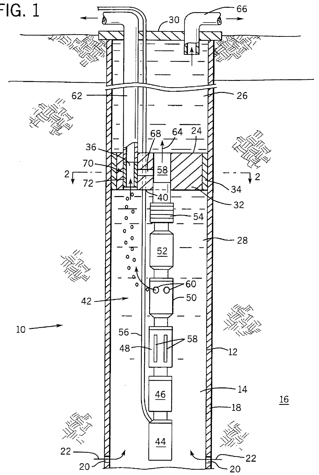
Turning now to the drawings, and referring first to FIG. 1, a completion system 10 is illustrated diagramatically. The completion system is shown deployed in a well 12 which consists of a wellbore 14 traversing one or more subterranean zones or horizons, including a production formation 16. In general, production formation 16 will include geological formations bearing fluids of interest, such as crude oil, gas, paraffin, and so forth. Wellbore 14 is defined by an annular casing 18 through which perforations 20 are formed adjacent to production formation 16. Fluids of interest flow from production formation 16 into casing 18 through perforations 20, as indicated by arrows 22.

It should be noted that while in the illustrated embodiment, and throughout the present description, reference is made to a wellbore which may be generally vertically oriented, the present technique is not intended to be limited to this or any particular well configuration. Thus, where appropriate, the technique ...


PUM


Abstract

A technique is disclosed for completion of a well, such as an oil and gas production well. A packer is positioned in the well to divide the well into upper and lower zones. The packer has multiple passageways between the upper and lower zones. A pumping system is positioned in the lower zone for displacing wellbore fluids flowing from a production formation. The pumping system may include a liquid/gas separator, and express gas-phase components through one of the passageways and liquid-phase components through another. A conduit conveys the gas-phase components to a desired location. The liquid-phase components are conveyed to a collection location in the annular region surrounding the conduit. The conduit may be used for positioning a chemical injection line within the well, or for receiving a parameter sensing unit. The chemical injection and parameter sensing may be performed independently of gas production, and without interruption of either gas or liquid production.

Description

1. Field of the InventionThe present invention relates to the field of submersible pumping systems for producing fluids, such as petroleum and gas, from wells. More particularly, the invention relates to a technique for producing fluids from wells by means of a submersible pumping system coupled to a packer through which a plurality of fluid passages are formed. The passages permit oil and gas to be produced through the separate passages of the packer, and through fluid conduits and annular portions of the well above the packer. The invention also provides a technique for sensing parameters in the vicinity of a submersible pumping system by means of the packer, as well as for injection of chemicals and other substances through at least one of the passages formed in the packer.2. Description of the Related ArtA variety of pumping systems have been devised and are currently in use for raising fluids from wells, such as petroleum production wells. In general, where a subterranean forma...

Claims


Application Information

Patent Timeline
Patent Type & Authority Patents(United States)
IPC IPC(8): E21B43/38E21B41/00E21B41/02E21B43/12E21B43/34
CPCE21B41/02E21B43/38E21B43/128
Inventor RIVAS, OLEGARIO S.
Owner CAMCO INT
Why Eureka
Try Eureka