Hydrodynamic apparatus for cleaning channels and for monitoring channels

a technology of hydrodynamic waterways and monitoring apparatuses, applied in the direction of sewer cleaning, hollow article cleaning, sewer system, etc., can solve the problems of power loss, no observation and determination, turbulence and swirl, etc., and achieve the effect of substantial water saving and energy saving

Inactive Publication Date: 2000-10-31
HORGER KURT +1
View PDF15 Cites 37 Cited by
  • Summary
  • Abstract
  • Description
  • Claims
  • Application Information

AI Technical Summary

Benefits of technology

It is possible with the solution according to the invention to adapt the channel-cleaning apparatus in the form of a bottom floor cleaner or of a channel-cleaning nozzle individually to the requirements of the respective application. The channel-cleaning apparatus can be varied in its weight depending on the employed water pressure or, respectively, to the respective pump power or, also electively, be furnished with the monitoring device. In this way, an optimizing of the cleaning process is achieved, whereby a substantial water saving and energy saving becomes possible. Furthermore, it is possible based on the employment of the camera module to distinguish already during the cleaning process heavily soiled channel sections, which require a several cleaning cycles, from lesser or not at all soiled channel sections, as well as to recognize damages of the pipe system and of the channel system.

Problems solved by technology

It is a disadvantage in this solution that the water impinges onto the bore base of the water connector, whereby turbulences and swirls and thus power losses are occurring.
Furthermore, it has been shown to be disadvantageous that the two connection bores meet each other at an acute angle.
A disadvantage of all known bottom floor cleaners, flushing heads, and channel-cleaner nozzles is that during the cleaning process no observation and no determination of the soiling state or, respectively, cleaning state of the channel and no recognition of damaged areas in the channel is possible.
At this time, the recognition of damaged areas in the channel require a cost-intensive channel inspection.
These cleaning apparatuses and manipulators exhibit however a substantially complicated constructive structure and a completely different mode of operation.
It is also a decisive disadvantage in connection with these cleaning apparatuses and manipulators that in the course of the cleaning operations there exists a high danger of damaging the transfer cables.
A further disadvantage of the above-described bottom floor cleaner is that its weight cannot be adapted to the respective pump power.

Method used


Image

  • Hydrodynamic apparatus for cleaning channels and for monitoring channels
  • Hydrodynamic apparatus for cleaning channels and for monitoring channels
  • Hydrodynamic apparatus for cleaning channels and for monitoring channels

Examples


Embodiment Construction

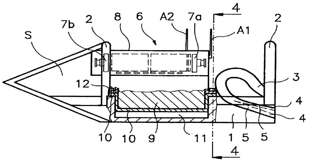
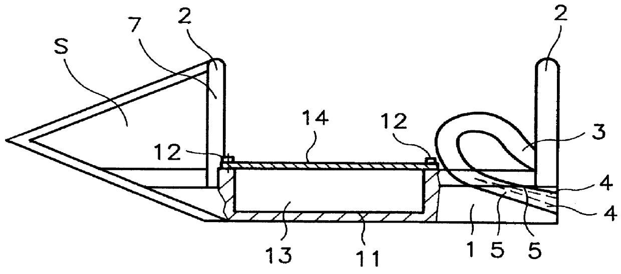
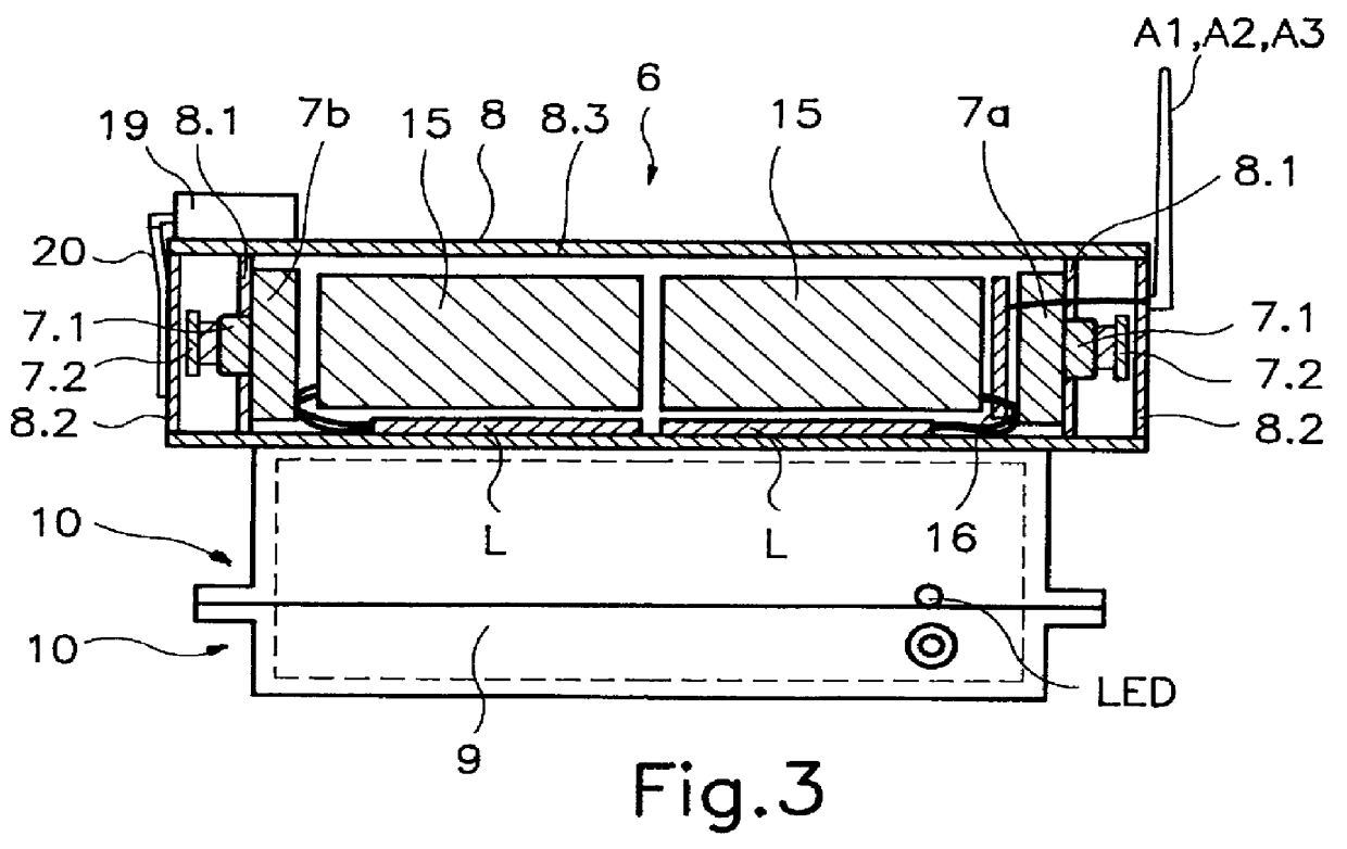
The hydrodynamic channel-cleaning apparatus according to FIG. 1 is formed in the shape of a bottom floor cleaner S and exhibits a base body 1 with two over-roll bars 2 and a connector for a water house as a pressurized water-entrance opening 3 and pressurized-water discharge openings 4 on the side of the water connector, wherein the pressurized water-entrance opening 3 is connected to the pressurized water-discharge openings 4 through water-guide conduits 5, formed as channels with circular cross-section. The longitudinal extension of the over-roll bars 2 is horizontally and perpendicular to the advance motion direction of the channel cleaning apparatus. The over-roll bars are disposed above the pressurized-water discharge openings 4. The over-roll bars 2 guard the water-guide conduits 5 against mechanical damage. A monitoring unit 6 is disposed at the base body 1. The monitoring unit 6 comprises two camera modules 7a and 7b, which camera modules 7a and 7b are disposed in a casing 8...


PUM


Abstract

A hydrodynamic apparatus for cleaning channels and for monitoring channels is provided for pipes and channels. A disadvantage of all conventional bottom floor cleaners, flushing heads, and channel-cleaning nozzles is that during the cleaning process no observation and determination of the soiling state or, respectively, of the cleaning state of the channel and no recognition of damaged areas in the channel is possible. According to the invention, a monitoring unit (6) is installed selectively in or at the channel-cleaning apparatus. For this purpose, for example, a hollow space (11) is furnished at the bottom floor cleaner (S), wherein the monitoring unit (6) is partly integrated into the hollow space (11). The monitoring unit (6) exhibits a camera module (7) or two camera modules (7a and 7b). A video emitter (15) is coordinated to each camera module (7). The transmission to a video receiver (V) is performed without cable wireless from the video emitter (15). The cleaning process can be followed in a monitor (M). As desired, also ballast material (12) can be filled into the hollow space (11).

Description

1. Field of the InventionThe invention relates to a cleaning apparatus and monitoring apparatus for hydrodynamic waterways and channels.2. Brief Description of the Background of the Invention Including Prior ArtThere are already numerous hydrodynamic apparatus for cleaning channels and for monitoring channels furnished as flow-through parts. Such hydrodynamic apparatus exhibits a water connector as a pressurized water-entrance opening, and recoil openings, directed rearwardly and connected to the pressurized water-entrance opening. The channel cleaning apparatus receives in the tube or channel an advance motion based on the recoil force of the water discharged.A channel cleaning apparatus furnished as a bottom or floor cleaning apparatus is described in the German printed petit patent document DE 93 08 910-U1, wherein the apparatus exhibits a closed and compact outer structure. The one-sided, rounded surface facilitates an automatic reerection. A flushing head with two sliding runne...

Claims


Application Information

Patent Timeline
Patent Type & Authority Patents(United States)
IPC IPC(8): B08B9/02B08B9/04E03F7/00E03F7/12E03F9/00B08B9/053
CPCB08B9/0495E03F9/00E03F7/12B08B2209/045
Inventor HORGER, KURTLUTZE, HANS
Owner HORGER KURT
Why Eureka
Try Eureka