
Sludge dehydrator

a technology of sludge dehydrator and sludge dehydrator, which is applied in the direction of water treatment parameter control, specific water treatment objectives, sedimentation settling tanks, etc., can solve the problems of increasing equipment treatment capacity, increasing costs, and requiring more extensive maintenan

Active Publication Date: 2021-07-27
REIJER PICOZZI AUGUSTO ERIC
View PDF3 Cites 2 Cited by
  • Summary
  • Abstract
  • Description
  • Claims
  • Application Information

AI Technical Summary

Benefits of technology

[0002]i) Water removal from ore sent to flotation, wherein two important benefits are obtained, namely, first the increase of the pulp or watery paste density of the ore will have a smaller volume of extracted water and consequently, it will increase the residence time in the primary flotation stage, thereby benefitting metallurgical recovery of valuable metal; in other words, a production increases and secondly, a substantial water saving is generated by directly recycling the previous size separation process performed by the hydrocyclons in the grinding stage.
[0003]ii) Dehydrating the concentrates that pass from the cleaning flotation to a the subsequent deeper cleaning process, where benefits are obtained in both the metallurgical recovery and the higher concentration or purity of the metal concentrate produced being caused by the longer residence time in the cleaning cells because of the smaller pulp or watery paste treated and therefore, a secondary benefit results from the water and reagents saving as an effect of the recycling possibility.
[0009]This substantial improvement of the submerged filter obeys to the fact that in its original system, cleaning of the filtration membrane is performed by injected air in countercurrent to the suction, whereby the filter cloth is inflated. The disadvantage of this system consists in that due to the gravity and air density of the liquid vis-à-vis the water or liquid; the air tends to get out through the upper part of the submerged filter and generates a short circuit; over half of the cloth or filtering membrane area remains without detaching the excess solid matter adhered thereto and therefore reduces the equipment treatment capacity. Added to this problem, after the cleaning process the submerged filter is full of air and once the suction system works again it loses it operational capacity and operation time for extracting the trapped air; moreover, the cloth positioning design should have a structure that is capable to bear the internal pressure generated during the blowing process in order to avoid its detachment. On the other hand, the sludge or modified submerged filter cleans the filtrating cloth or membrane with a scraper and previously stops the suction and slightly increases the internal pressure, making it equal to the external pressure in order to change the surface of the cloth and release the adhered solid. This innovation permits to operate with the thicker sludge or watery pastes and thus expand its field of application.

Problems solved by technology

The disadvantage of this system consists in that due to the gravity and air density of the liquid vis-à-vis the water or liquid; the air tends to get out through the upper part of the submerged filter and generates a short circuit; over half of the cloth or filtering membrane area remains without detaching the excess solid matter adhered thereto and therefore reduces the equipment treatment capacity.
They perform the solid-liquid separation through natural settling of the solids, generally by accelerating the precipitation with flocculants or coagulants.Although centrifugal machinery can achieve a good separation between phases, the equipment evidences a certain mechanic sophistication which raises their cost and requires more exhaustive maintenance.

Method used


Image

  • Sludge dehydrator
  • Sludge dehydrator
  • Sludge dehydrator

Examples


Embodiment Construction

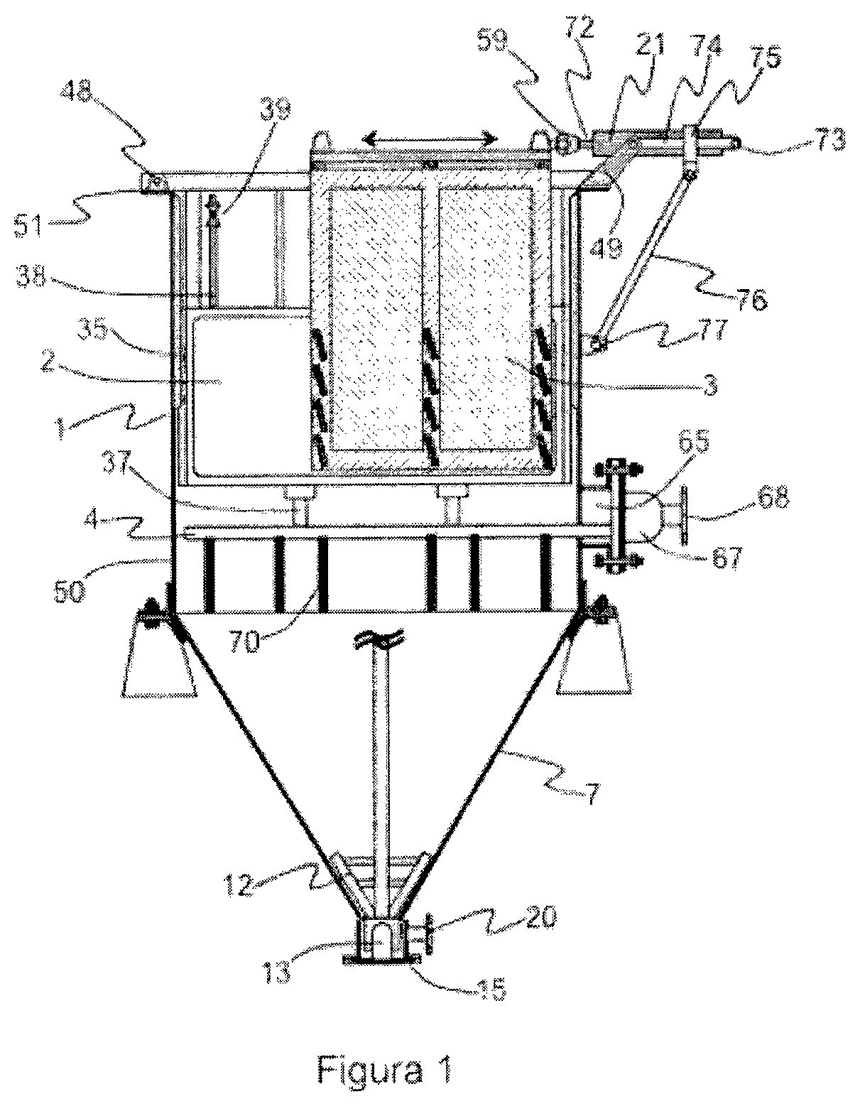
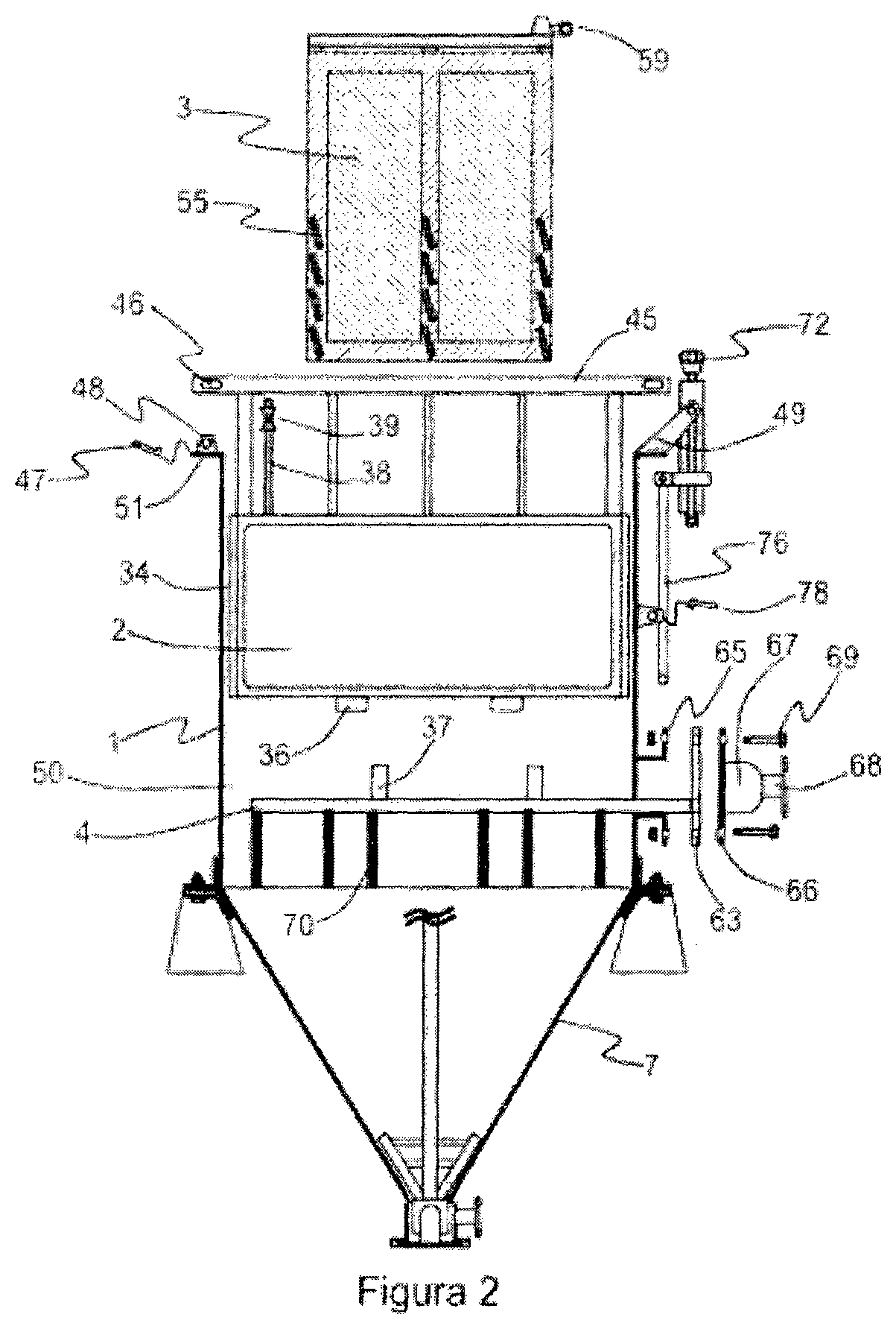
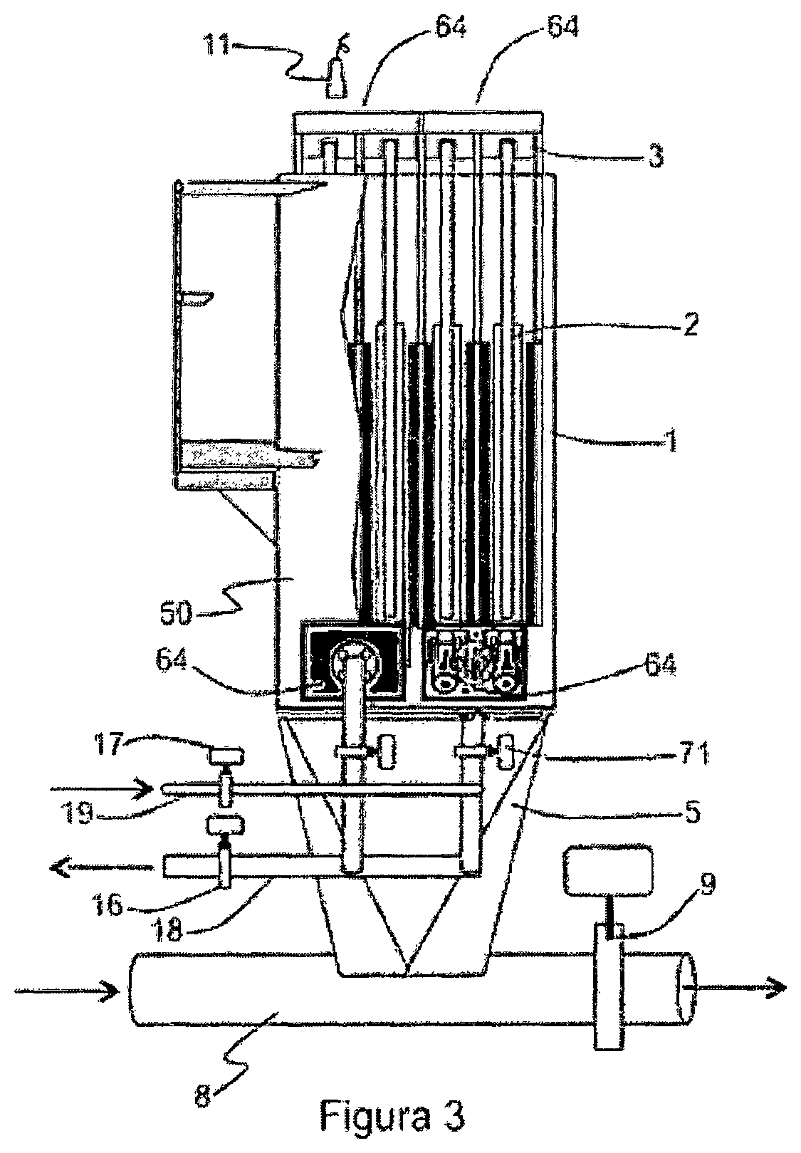
[0028]With reference to FIGS. 1 and 2, the “sludge dehydrator” invention (1) consists of an equipment for extracting portions of clarified or partially clarified water from sludge or watery pastes, as well as from turbid water having substantial contents of solids in suspension, in all cases by increasing the density of the muddy material or watery paste. The mechanism for removing the clarified or partially clarified water is carried out with a modified submerged filter, which reaches a high capacity vis-à-vis that of the original Chilean Patent No. 44,264; in this way the dehydrated sludge is settled, concentrated and discharged through the lower cone of the “sludge dehydrator” (1).

[0029]The modified submerged filter consists of the set made up by a suction plate (2) and a cleaning car (3). The suction plate (2) is connected to the suction pipe (4) that extracts the absorbed water; the solids are retained in the filtering cloth or membrane (25); the cleaning car (3) is moved and t...


PUM

PropertyMeasurementUnit
densityaaaaaaaaaa
concentrationaaaaaaaaaa
fluidityaaaaaaaaaa

Abstract

The “sludge dehydrator” equipment is a machine that permits to remove low turbidity water from sludge or watery pastes of industrial or mining origin, with the following objectives:To optimize ore recovery processes such as flotation by means of an increase of the sludge density;To thicken sludge or watery pastes for optimizing the filtering and drying processes, as well as to dispose of mining tailings;To concentrate and dispose of solids in suspension and to recover and recycle clean or clarified water.The “sludge dehydrator” equipment has been designed on the basis of a rectangular tank provided with the necessary infrastructure for containing inside a series of suction plates being connected to a vacuum system, through which the process of solid-liquid separation is carried out and, on the other hand, to contain the cleaning mechanism—the cleaning car—with its motor system made up by pneumatic or hydraulic components required to clean suction plates the filtering medium and to keep them permanently operative.In accordance with the “sludge dehydrator” feeding and the design of the lower or bottom cone of the rectangular tank will benefit to be derived from the industrial and mining operation.

Description

BACKGROUND OF THE INVENTION[0001]The invention concerns a machine designed for removing water from sludge or watery pastes and also to clarify water being necessary works in the mining works. The machine that is the subject matter of the invention removes water from sludge or slime including a negligible quantity of suspended solids as compared to the original content, thereby increasing the density of the sludge material and consequently reducing its volume. The water removal process from sludge or watery pastes is very useful in mining operations and also in other diverse industrial activities. Thus, the industrial benefit generated by the invention denominated “Sludge Dehydrator” is wide and preferably applied to several mining works, such as for example:[0002]i) Water removal from ore sent to flotation, wherein two important benefits are obtained, namely, first the increase of the pulp or watery paste density of the ore will have a smaller volume of extracted water and consequen...

Claims


Application Information

Patent Timeline
Patent Type & Authority Patents(United States)
IPC IPC(8): C02F11/12B01D21/00B01D21/02B01D21/24B01D21/30B01D29/05B01D29/64B01D29/52B01D63/08B01D65/02B01D29/60C02F11/121B01D29/15C02F1/00C02F1/24C02F103/10
CPCC02F11/121B01D21/0012B01D21/10B01D21/2405B01D21/2444B01D21/2494B01D21/30B01D21/302B01D29/05B01D29/15B01D29/52B01D29/605B01D29/6423B01D29/6484B01D63/08B01D65/02C02F1/008B01D2201/0415B01D2201/16B01D2201/34B01D2221/04B01D2313/04B01D2313/06B01D2313/16B01D2315/06B01D2317/04B01D2321/30C02F1/24C02F2001/007C02F2103/10C02F2201/005C02F2209/40C02F2209/42C02F2303/16
Inventor REIJER PICOZZI, AUGUSTO ERIC
Owner REIJER PICOZZI AUGUSTO ERIC
Learn More