Mud flap lifter

a technology of mud flaps and lifters, which is applied in the directions of transportation, transportation items, loading/unloading vehicle arrangments, etc., can solve the problems of damage to mud flaps, illegal trucks traveling over highways with damaged mud flaps, and affecting the safety of drivers, etc., to achieve the effect of easy use, low maintenance and economic manufactur

Inactive Publication Date: 2000-10-31
MEYER DARIN
View PDF20 Cites 16 Cited by
  • Summary
  • Abstract
  • Description
  • Claims
  • Application Information

AI Technical Summary

Benefits of technology

In the Moore system, a cable attached to the outside of each mud flap is pulled from above, folding the mud flap as it is lifted upward and rearward away from the truck tires. While this does not provide full retraction of the mud flap from behind the tires, the movement of the mud flap is sufficient to prevent damage without requiring a complex retraction system. However, the problem with cable-actuated systems such as disclosed by Moore is that the cables, because they are necessarily exposed and are located above and rearward of the mud flaps, can themselves become damaged by weather or contact with obstacles and loads at the rear of the truck. Furthermore, the attachment of the cables is often made directly to the mud flaps. This can cause cracking and damage to the mud flaps because the mud flap is weakened at the point of attachment since it is not designed to experience a pulling force at that point. Finally, cable systems such as the Moore system require that the mud flap be altered to receive the cable attachment, thereby increasing the cost of installation and making replacement of mud flaps more difficult and more costly. There is therefore a need in the art for an economical mud flap retraction system which prevents damage to mud flaps during normal operation of trucks, such as dump trucks, yet is economical and easy to use.
In order to meet the needs in the art for an improved mud flap retraction system as explained above, the present mud flap lifter has been devised. The present device departs from the prior art in that it pushes the mud flap from the inside, rather than pulling it from the outside. This permits the mud flap lifting mechanism to be protected by partial enclosure underneath existing truck structures. It does not project rearward of the normal mud flap position when not in use and therefore it is much less susceptible to damage than the prior art devices. The present invention employs simple push bars which swing about a pivot from the underside of the truck body behind the mud flap to lift the flap upward and rearward so that it is held a safe distance from the rear tires. This distance prevents the mud flap from being pinched between obstacles and the rear tires so that damage to the mud flaps will not occur. Because simple push bars are used, there is no requirement that the mud flaps be altered since there is no direct attachment between the lift mechanism and the mud flap. Because of the way in which the present push bars work, lifting forces are distributed over a greater area of the mud flap compared to other systems, such as those requiring direct cable attachment. Also because there is no direct attachment between the lift mechanism and the mud flap, mud flaps can be replaced or interchanged without any impediment caused by the mud flap lifting system.

Problems solved by technology

Problems arise when mud flaps behind the rear wheels of trucks contact objects behind the truck as it is backing up.
When this happens, the mud flaps are pinched against the rear wheels and are often torn away or otherwise damaged.
Damaged mud flaps can disable a vehicle since federal law requires that all such trucks in interstate commerce include mud flaps in good condition and of sufficient length.
Trucks traveling over the highway with damaged mud flaps are illegal and may be subject to fines and other penalties.
The systems which retract mud flaps into an enclosure are very expensive and the mud flap can become jammed inside the enclosure by mud and other debris.
While this does not provide full retraction of the mud flap from behind the tires, the movement of the mud flap is sufficient to prevent damage without requiring a complex retraction system.
However, the problem with cable-actuated systems such as disclosed by Moore is that the cables, because they are necessarily exposed and are located above and rearward of the mud flaps, can themselves become damaged by weather or contact with obstacles and loads at the rear of the truck.
This can cause cracking and damage to the mud flaps because the mud flap is weakened at the point of attachment since it is not designed to experience a pulling force at that point.
Finally, cable systems such as the Moore system require that the mud flap be altered to receive the cable attachment, thereby increasing the cost of installation and making replacement of mud flaps more difficult and more costly.

Method used


Image

  • Mud flap lifter
  • Mud flap lifter
  • Mud flap lifter

Examples


Embodiment Construction

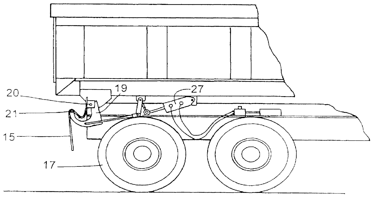
Referring now to FIG. 1, the present invention is shown installed at the rear of a typical dump truck. The truck includes body 11 which is tiltably affixed to frame 13. Mud flap 15 is shown in its "at rest" position for over-the-road travel, the mud flap being held at a fixed attachment point and extending the proper distance downward and behind rear tire 17. Pneumatic cylinder 19 moves a linkage which will be described in greater detail with regard to FIG. 4 that presses a push bar 21 in the form of a cylindrical rod into the inside surface of mud flap 15. The pneumatic cylinder is fed by air lines 23 that are controlled by electromechanical valve 25. The action of the push bar lifts and moves the mud flap rearward.

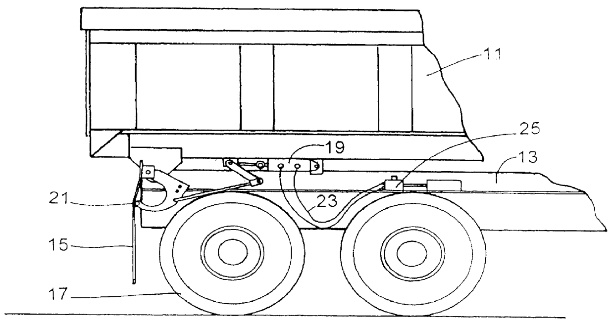
Referring now to FIG. 2, the present invention is shown with the mud flaps in their retracted position. In this position, the pneumatic cylinder 19 has retracted, moving the push bar 21 against the back of mud flap 15, lifting it and moving it rearward away from rear tir...


PUM


Abstract

A mud flap lifting system for trucks pushes the mud flaps from their inside surface upward and rearward away from the rear tires. Push bars swing about a pivot from the underside of the truck body directly behind the mud flap. The push bars include C-shaped arms which receive the upper portion of the folded mud flap as it is retracted. Fully retracted, the mud flap is compactly folded so that it is less susceptible to damage. The lift mechanism is pneumatically powered by a single centrally-located cylinder which actuates twin linkages on either side of the truck through a transverse pivoting axle so that both mud flaps may be retracted simultaneously by a single pneumatic actuator.

Description

This invention relates to movable or retractable mud flaps for vehicles, particularly dump trucks. More specifically, it relates to actuators for moving mud flaps which are pneumatically powered.BACKGROUND OF THE INVENTION AND DESCRIPTION OF PRIOR ARTProblems arise when mud flaps behind the rear wheels of trucks contact objects behind the truck as it is backing up. When this happens, the mud flaps are pinched against the rear wheels and are often torn away or otherwise damaged. Damaged mud flaps can disable a vehicle since federal law requires that all such trucks in interstate commerce include mud flaps in good condition and of sufficient length. Trucks traveling over the highway with damaged mud flaps are illegal and may be subject to fines and other penalties.There have been suggested many different devices for moving or retracting dump truck mud flaps in order to cure the above-stated problem of damage caused to the mud flaps while backing up the truck. These devices are describ...

Claims


Application Information

Patent Timeline
Patent Type & Authority Patents(United States)
IPC IPC(8): B62D25/16B60P1/04B60P1/28B62D25/18
CPCB62D25/188B60P1/283
Inventor MEYER, DARIN
Owner MEYER DARIN
Why Eureka
Try Eureka