Motor stator winding tool

a technology of motor stator and winding tool, which is applied in the field of winding tools, can solve problems such as time-consuming and difficult problems

Inactive Publication Date: 2000-11-07
TRW INC
View PDF13 Cites 26 Cited by
  • Summary
  • Abstract
  • Description
  • Claims
  • Application Information

AI Technical Summary

Problems solved by technology

This task is typically done by hand and can be diff

Method used


Image

  • Motor stator winding tool
  • Motor stator winding tool
  • Motor stator winding tool

Examples


Embodiment Construction

The present invention relates to a tool for use in the manufacture of an electric motor. In particular, the present invention relates to a winding tool for assisting in connecting pairs of motor stator winding leads and cutting of the connected pairs of leads to a predetermined length.

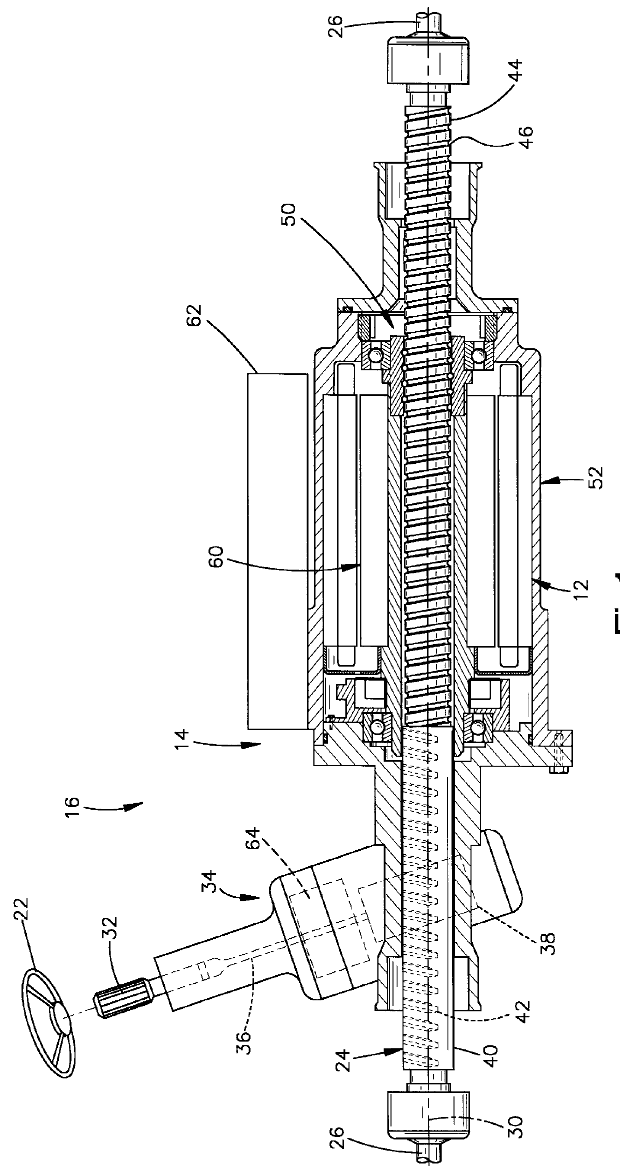
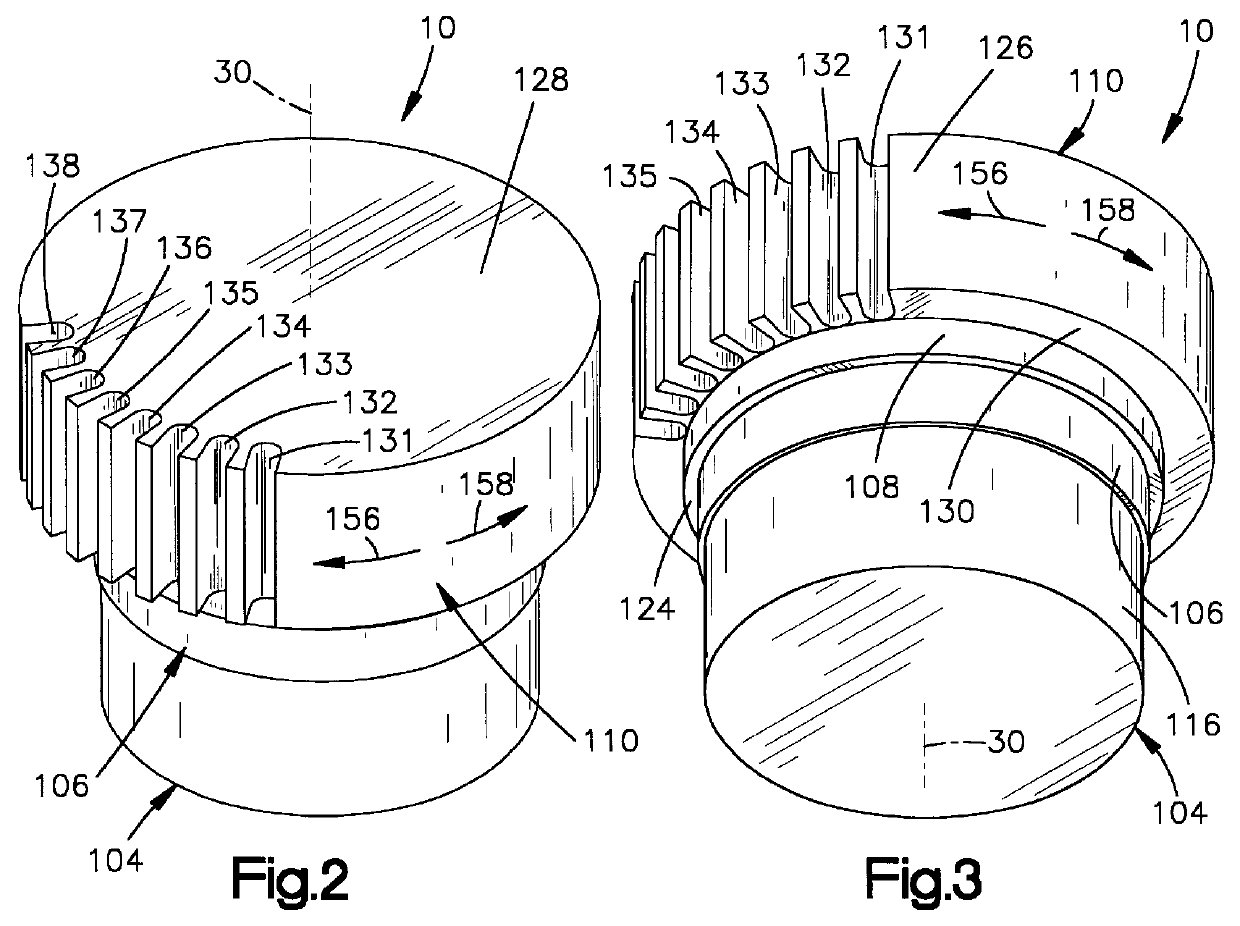
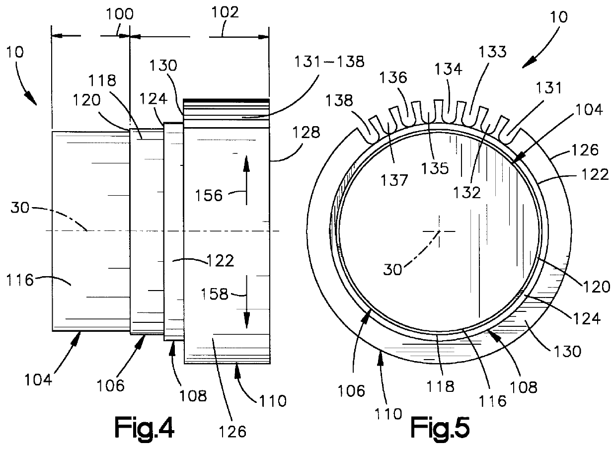
As representative of the present invention, FIGS. 2-5 illustrate a winding tool 10 for use in winding the motor stator 12 (FIGS. 1 and 6-10) of a motor 14 which forms part of a vehicle power assist steering system 16.

The steering system 16 (FIG. 1) includes a driver-operated steering wheel 22 operatively connected to a rack or steering member 24. The steering member 24 is coupled with the steerable wheels (not shown) of a vehicle through tie rods 26. The steering member 24 extends along an axis 30 of the steering system 16.

The vehicle steering wheel 22 is connected for rotation with an input shaft 32 which extends into a pinion housing 34. The input shaft 32 is mechanically coupled by a torsion bar 36,...


PUM

PropertyMeasurementUnit
Lengthaaaaaaaaaa
Diameteraaaaaaaaaa

Abstract

A winding tool (10) is used for connecting pairs of motor stator winding leads (91b-98b, 91c-98 c) and cutting of the connected pairs of leads to a predetermined length. The winding tool (10) includes a first part (100) received in the rotor space (88) in the motor stator (12) and a second part (102) projecting from a first end portion (72) of the motor stator. The first part (100) of the winding tool (10) has a cylindrical outer surface (116) engageable in an interference fit with a cylindrical inner surface (86) of the motor stator core (80) to resist radial and axial movement of the winding tool relative to the motor stator (12). The winding tool (10) has a plurality of slots (131-138) spaced circumferentially about an axis (30) and extending along an outer surface (126) of the second part (102) of the winding tool (10). The number of slots (131-138) is equal to the number of magnetic poles of the motor stator (12). The slots (131-138) have an axial length approximately equal to the predetermined length of the connected pairs of leads (91b-98b, 91c-98c).

Description

1. Technical FieldThe present invention relates to a winding tool for use in winding a stator of an electric motor. In particular, the present invention relates to a winding tool for use in winding a stator of an electric motor used in an electric power assist steering system for a vehicle.2. Description of the Prior ArtA known type of vehicle steering system includes a rack which is movable linearly to effect turning movement of the steerable wheels of the vehicle. Movement of the rack is assisted by an electric assist motor. The motor has a stator and a rotor. The rack extends axially through the rotor. Actuation of the motor causes the rotor to rotate a ball nut which is engaged with a screw portion of the rack. The rotation of the ball nut causes the rack to move linearly to effect turning movement of the steerable wheels of the vehicle.The stator includes a metal core and a plurality of windings (coils) on the metal core. During manufacture of the stator, the lead wires which a...

Claims


Application Information

Patent Timeline
IPC IPC(8): H02K15/00
CPCH02K15/0056H02K15/0075Y10T29/53143Y10T29/49009H02K15/0068
Inventor BUGOSH, MARK J.
Owner TRW INC
Why Eureka
Try Eureka