Lifting apparatus

a technology of lifting apparatus and lifting rod, which is applied in the direction of lifting equipment, curtain suspension device, lighting support device, etc., can solve the problems of high cost, high risk of work, and accident caused

Inactive Publication Date: 2000-11-07
ARAMAKI TEKUNIKA
View PDF12 Cites 50 Cited by
  • Summary
  • Abstract
  • Description
  • Claims
  • Application Information

AI Technical Summary

Benefits of technology

Another object of the present invention is to provide a lifting apparatus which can be subjected to maintenance work at a low place by lowering the lifting apparatus even if the lifting mechanism fails.
In accordance with another aspect of the present invention, the lifting apparatus comprises: a fixed part to be fixed at a high place, a lifting part which comprises an installation to be installed at the fixed part and an electric motor for at least moving up the lifting part and which is suspended from the fixed part by a wire cable to move up and down, a locking device for locking the lifting part to the fixed part, which comprises a releasing member for releasing the locking of the lifting part and the fixed part, and a speed reducer for reducing speed of the lifting part, through which the wire cable is winched by the electric motor; wherein the lifting part is moved down by self-weight.

Problems solved by technology

However, in the above-mentioned conventional methods, there is a problem that the cost therefor is increased.
Further, there is much possibility that an accident is caused because all the steps of the work are performed at a high place.
Therefore, dangerous work at a high place is only work for fixing the small and lightweight fixed part.

Method used


Image

  • Lifting apparatus
  • Lifting apparatus
  • Lifting apparatus

Examples


second application example

FIG. 4 is a perspective view of a set of two road lamps, which is a second application example of the lifting apparatus shown in FIG. 1. FIG. 5 is a perspective view showing a lowering operation of the road lamps.

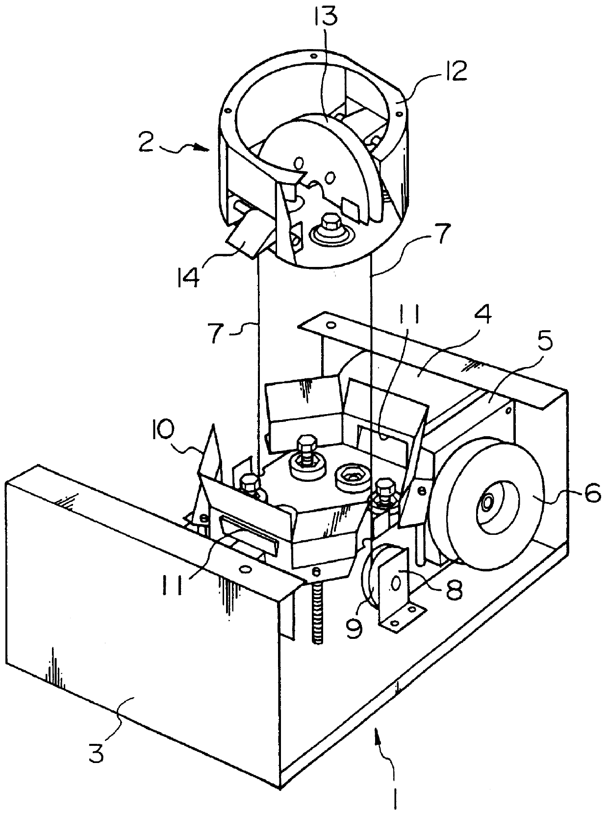
In FIGS. 4 and 5, like the lifting apparatus shown in FIG. 1, reference numeral 1 denotes a lifting part, 2 denotes a fixed part, 3 denotes a lifting frame, 7 denotes a wire cable, and 12 denotes an upper frame. Further, reference numeral 19 denotes a street pole, 20 denotes an arm, and 21 denotes a box-type of road lamp.

In this application example, as shown in the figures, the upper frames 12 and 12 of the fixed parts 2 and 2 are attached and fixed to the lower surfaces of the arms 20 and 20 extending from the upper end of the street pole 19, respectively. On the other hand, the box-type of road lamps 21 and 21 are attached and fixed to the lower surfaces of the lifting frames 3 and 3 of the lifting parts 1 and 1 suspended from the upper frames 12 and 12 through wire cable...

third application example

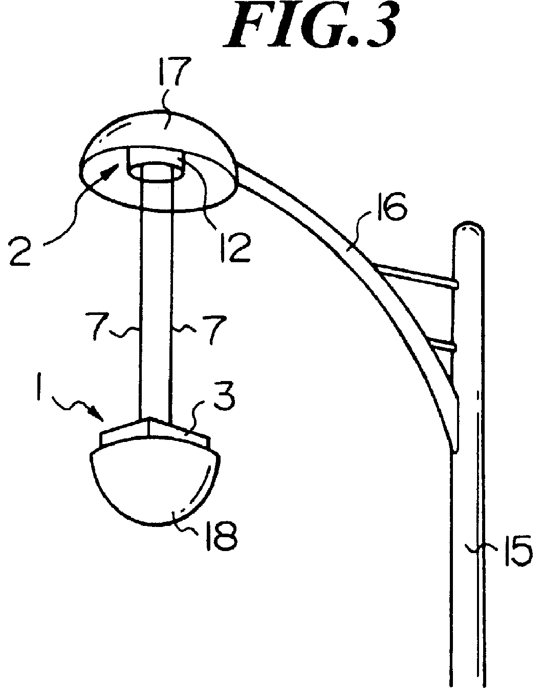
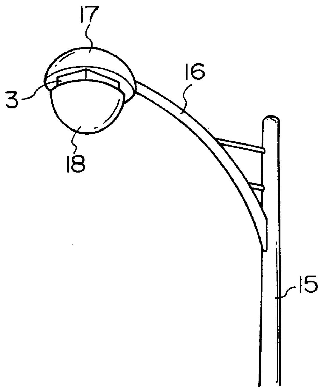
FIG. 6 is a perspective view of a ceiling-type of lighting apparatus, which is a third application example of the lifting apparatus shown in FIG. 1. FIG. 7 is a perspective view showing a lowering operation of the lighting apparatus.

In FIGS. 6 and 7, like the lifting apparatus shown in FIG. 1, reference numeral 1 denotes a lifting part, 2 denotes a fixed part, 3 denotes a lifting frame, 7 denotes a wire cable, and 12 denotes an upper frame. Further, reference numeral 22 denotes a ceiling, and 23 denotes a lighting apparatus.

In this application example, as shown in the figures, the upper frame 12 of the fixed part 2 is attached and fixed to the ceiling 22 of a room. On the other hand, the lighting apparatus 23 is attached and fixed to the lower surface of the lifting frame 3 of the lifting part 1 suspended from the upper frame 12 through the wire cable 7.

Therefore, when the installation work is performed, it is only necessary to fix the small and lightweight fixed part 2 (upper frame...

fourth application example

FIG. 8 is a perspective view of a ceiling-type of chandelier, which is a fourth application example of the lifting apparatus shown in FIG. 1. FIG. 9 is a perspective view showing a lowering operation of the chandelier.

In FIGS. 8 and 9, like the lifting apparatus shown in FIG. 1, reference numeral 1 denotes a lifting part, 2 denotes a fixed part, 3 denotes a lifting frame, 7 denotes a wire cable, and 12 denotes an upper frame. Further, reference numeral 24 denotes a ceiling, and 25 denotes a chandelier.

In this application example, as shown in the figures, the two upper frames 12 and 12 of the fixed parts 2 and 2 are attached and fixed to the ceiling 24 of a room. On the other hand, the chandelier 25, which is a lighting apparatus, is attached and fixed to the lower surfaces of the lifting frames 3 and 3 of the lifting parts 1 and 1 suspended from the upper frames 12 and 12 through the wire cables 7 and 7, respectively.

Therefore, when the installation work is performed, it is only nec...


PUM


Abstract

A lifting apparatus for installation or maintenance of an elevated installation in order to simplify installation work and perform maintenance work at a lower place. The lifting apparatus comprises a fixed part to be fixed at a high place, and a lifting part which comprises an installation to be installed at the fixed part and a power source for at least moving up the lifting part and which is suspended from the fixed part to move up and down.

Description

1. Field of the InventionThe present invention relates to a lifting apparatus for an elevated installation, e.g., a road lamp, a lighting apparatus to be attached to a ceiling, a signal, an air conditioning system to be attached to a ceiling, an apparatus to be suspended from a ceiling for a stage and a construction having a large space, furniture, an alarm, a smoke detector and a signboard.2. Description of Related ArtFor example, when an elevated installation such as a road lamp, is installed at a high place, or when maintenance work for such an elevated installation is performed, three methods have been used conventionally: (1) a scaffold is constructed, (2) a vehicle for high lift work is used, and (3) a lifting apparatus for maintenance is installed at a high place.However, in the above-mentioned conventional methods, there is a problem that the cost therefor is increased. Further, there is much possibility that an accident is caused because all the steps of the work are perfor...

Claims


Application Information

Patent Timeline
Patent Type & Authority Patents(United States)
IPC IPC(8): B66D1/00B66D1/60F21V21/36F21V21/38B66F7/02B66F19/00F21S8/08
CPCB66D1/60F21V21/38F21S8/086F21S8/04
Inventor ARAMAKI, NORIYOSHI
Owner ARAMAKI TEKUNIKA
Why Eureka
Try Eureka