File adapter for power saw tool

a technology for power saws and adapters, which is applied in the field of file adapters for power saws, can solve the problems of critical bending moments

Inactive Publication Date: 2000-11-07
FUSCO IVALEE
View PDF3 Cites 14 Cited by
  • Summary
  • Abstract
  • Description
  • Claims
  • Application Information

AI Technical Summary

Problems solved by technology

It will be apparent that the file to chuck attachment is essentially a hinge and therefore bending moments are critically high.

Method used


Image

  • File adapter for power saw tool
  • File adapter for power saw tool
  • File adapter for power saw tool

Examples


Embodiment Construction

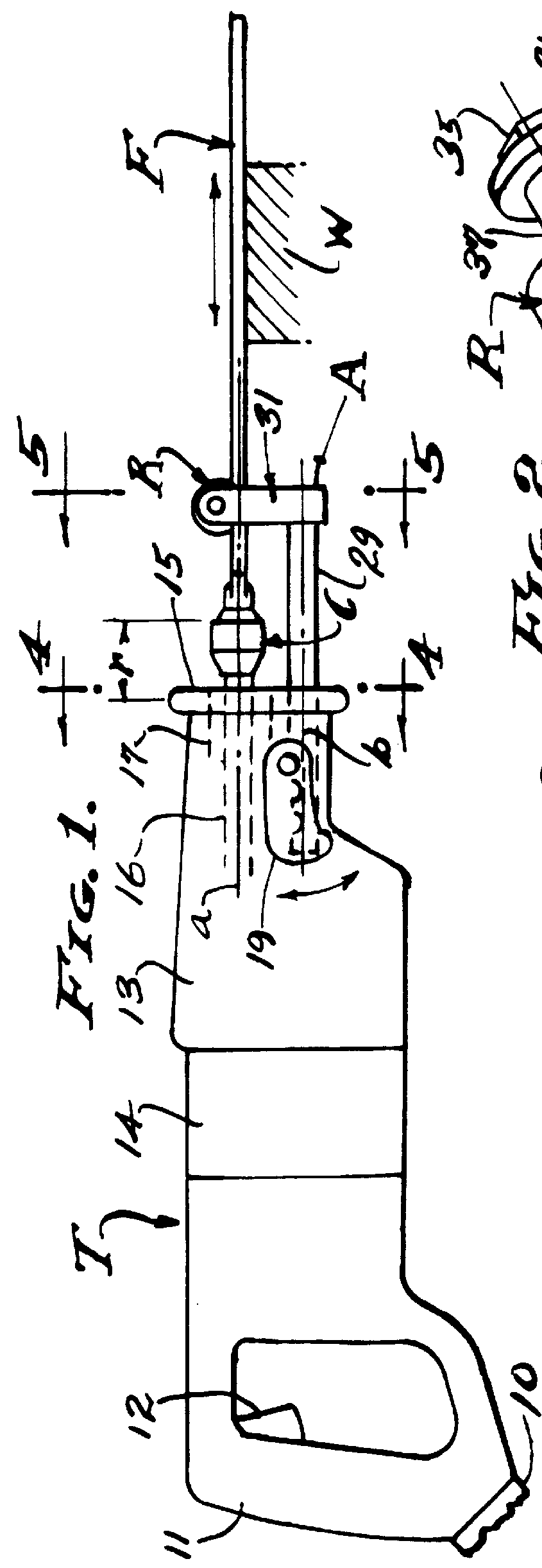
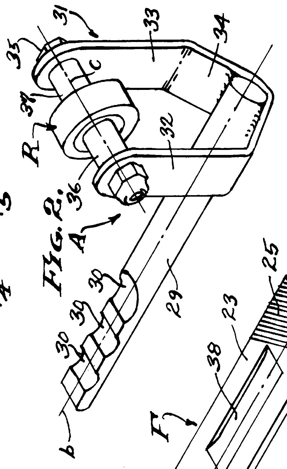
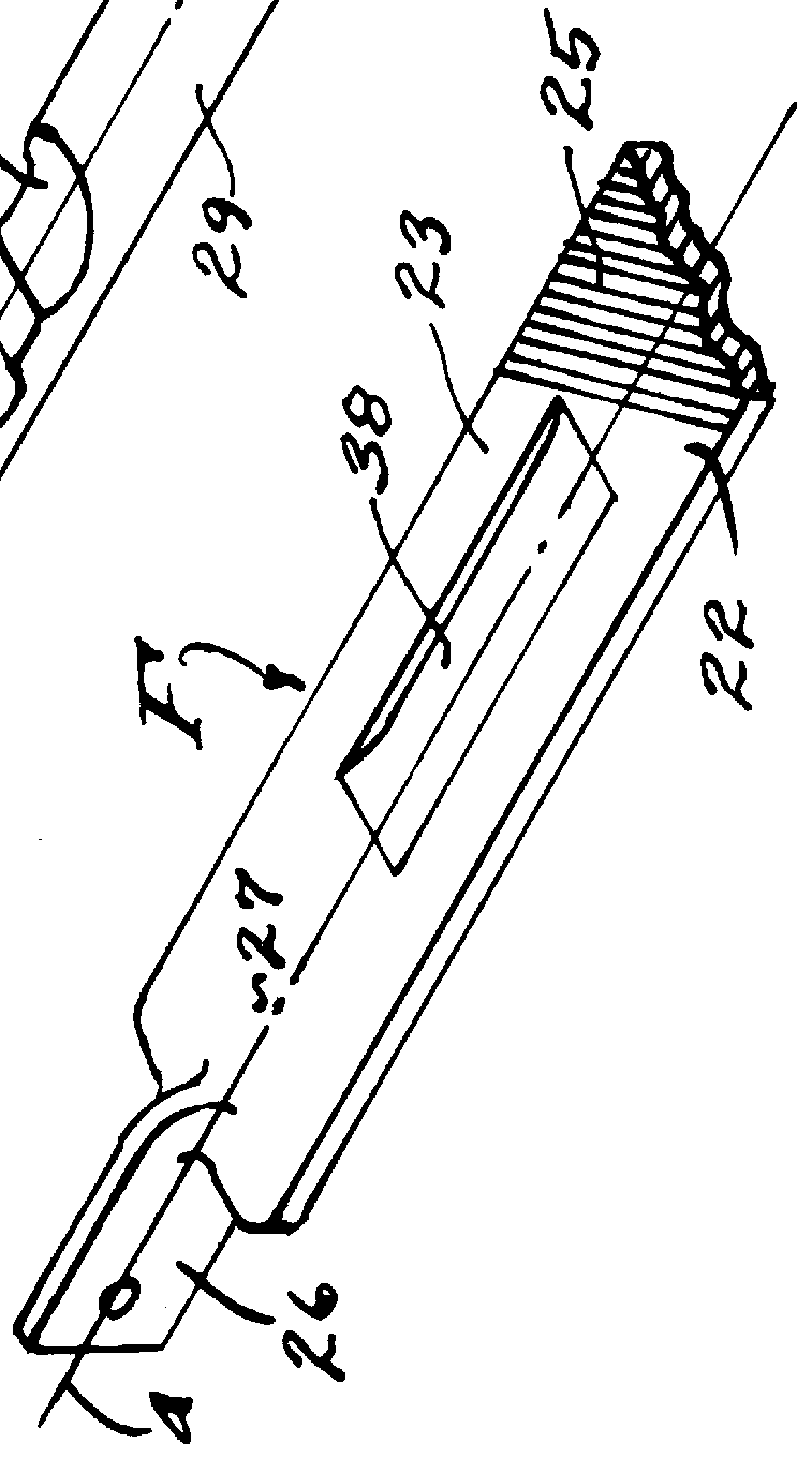
Referring now to the drawings, the file adapter A herein disclosed is useful as an aftermarket attachemnt to a hand held power saw tool T as clearly illustrated in FIG. 1. However, it is to be understood that the features involved in this combination of power tool and file adapter can be a "Power File Tool" per se. And, the file file F is a modified hand file as clearly illustrated in FIG. 3, and this file can be a special file with abrasive cutting means adapted to use in said Power File Tool.

The power saw tool T is electrically operated through a power cord attachment 10 and hand grip 11 with a trigger switch 12 for controlled manipulation. Intermediate the hand grip 11 and a power head 13 there is an electric motor drive 14, the power head being characterized by a flat front face 15 through which a ram-rod 16 reciprocates a chuck C on a reciprocating axis a. The chuck C is shown in its extreme forward reciprocal position, and its rearward travel indicated by the dimension r. As s...


PUM

PropertyMeasurementUnit
resistanceaaaaaaaaaa
pressureaaaaaaaaaa
lateral pressuresaaaaaaaaaa

Abstract

A motor driven power hand tool and adapter reciprocating a modified hand file in pressured engagement with a work piece by manipulating a lever resistance intermediate the opposite ends of a file which becomes a second class lever operating with a fulcrum at its reciprocally driven end and with work force applied at its other end, the invention residing in the adapter that guides the file as an aftermarket device and in combination with the power hand tool.

Description

This invention relates to hand operated power tools of the type for reciprocating saw blades and the like. Such tools are electrically operated and characterized by a driving head that reciprocates a ram rod to which a saw blade or the like is attached as by means of a set screw or chuck. A feature of these power saw tools is a shoe that slidably engages and limits the penetration of the saw blade into said work. A heavy duty power saw tool of the type under consideration is shown in FIG. 1 of the drawings herein, with the aforesaid guide shoe removed and replaced by the file adapter of the present invention. Also, a common hand file (modified) replaces a saw blade for which this particular power tool is designed.Heretofore, slender elongated saw blades of thin cross section (0.040" to 0.050"), and sander attachments, have been operated by such power tools, so as to reciprocate against and through work pieces, and various guide mechanisms have been associated with the controlling sh...

Claims


Application Information

Patent Timeline
Patent Type & Authority Patents(United States)
IPC IPC(8): B23D57/00B23D67/00B23D67/12
CPCB23D57/0076B23D67/12Y10T407/18Y10T407/1825Y10T407/182Y10T407/1805
Inventor FONTAINE, ROBERT R.
Owner FUSCO IVALEE
Why Eureka
Try Eureka