Center post tire changing apparatus

a tire changing and center post technology, applied in the direction of wheel mounting apparatus, manufacturing tools, instruments, etc., can solve the problems of high cost and technical skill required to operate the equipment, many automated systems prohibitive for certain users, and many tire changing apparatuses, both automated and manually operated, are not particularly suited to use with a wide range of tire sizes and/or wheel rim types. , to achieve the effect of mounting and demounting a wide range of tires

Inactive Publication Date: 2000-11-14
SUMMIT TOOL
View PDF16 Cites 14 Cited by
  • Summary
  • Abstract
  • Description
  • Claims
  • Application Information

AI Technical Summary

Benefits of technology

It is still another object of the present invention to provide a center post tire changing apparatus, as above, which is capable of mounting and demounting a wide range of...

Problems solved by technology

The extremely high cost and technical skill required to operate the equipment makes many of the automated systems prohibitive for certain users, particularly low volume users or those dealing with specialty tires.
Unfortunately, many tire changing apparatus, both automated and manually-operated, are not particularly suited for use with a wide range of tire sizes and/or wheel rim types.
Disadvantageously, however, all of these rim clamping devices or apparatus require significant clamping force be applied to the wheel rims in order to secure the wheel to the apparatus and prevent rotation of the wheel during the mounting or demounting operations.
Oftentimes, the amount of clamping force may be excessive, thereby causing wheel deformation or damage to the rim of the wheel, particularly where small, lighter (e.g., aluminum) wheels are employed.
However, placement of the tire on the rim, like the rim clamping devices, often leads to damaged or deformed rims.
Moreover, use of a plate might also deform or damage the wheel near its center.
While the use of pin blocking mechanisms avoids the potential for wheel deformation inherent with rim clamping and the like, there are clear disadvantages to using an apparatus limited to only this means ...

Method used


Image

  • Center post tire changing apparatus
  • Center post tire changing apparatus
  • Center post tire changing apparatus

Examples


Embodiment Construction

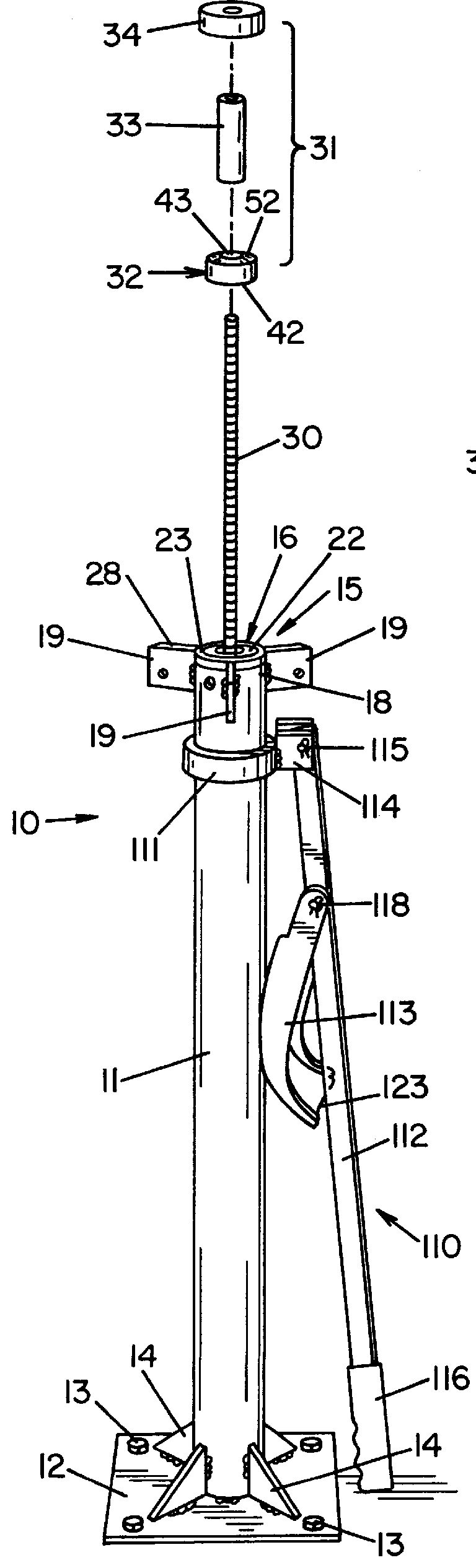
One representative embodiment of a center post tire changing apparatus made in accordance with the concepts of the present invention is indicated generally by the numeral 10 in FIG. 1A of the accompanying drawings. The tire changing apparatus 10 may include a support post 11 and a base plate 12 mounted to the lower end thereof. The base plate 12 is preferably secured to a floor or other surface suitable for providing stability to the apparatus 10 by any means known in the art such as by bolts 13. The support post 11 is preferably a hollow cylinder fabricated from steel pipe or other suitable material sufficient to carry out the requirements of the present invention. In particular, the support post 11 should be sturdy and rigid enough to support the operation of a bead breaker as described hereinbelow and the weight of a wheel and a tire, as well as the torque associated with mounting and demounting the tire from the wheel. For embodiments with relatively long support posts potential...


PUM


Abstract

A center post tire changing apparatus for mounting or demounting a tire from a wheel includes an elongated support post having a wheel support assembly disposed on one end of the support post and a center post connected to and extending upwardly from the wheel support assembly and in coaxial alignment with the support post. A wheel securing assembly is disposed upon the center post, wherein the wheel is securely mounted on the center post between the wheel support assembly and the wheel securing assembly. A bead beaker is preferably permanently secured to the support post and is noted to be continuously adjustable thereon.

Description

The present invention relates generally to an apparatus designed for breaking the bead of a tire and, separately, for effectively holding a tire in place while mounting and / or demounting the tire from a wheel rim. More particularly, the present invention relates to an apparatus of the type having a center post over which the tire may be positioned on the apparatus prior to mounting and / or demounting the same. Specifically, the present invention relates to a manually operated, center post tire changing apparatus capable of accommodating a range of tire sizes and practically all types of wheel rims.Modern tire changing equipment today ranges from a variety of simple, manually-operated systems to complex, automated, pneumatically-driven systems. The extremely high cost and technical skill required to operate the equipment makes many of the automated systems prohibitive for certain users, particularly low volume users or those dealing with specialty tires. Manually-operated equipment, t...

Claims


Application Information

Patent Timeline
IPC IPC(8): B60C25/00B60C25/01B60C25/02
CPCB60C25/02B60C25/01
Inventor KLISKEY, ROGER
Owner SUMMIT TOOL
Why Eureka
Try Eureka