Since the
coating of a cathodic workpiece is largely merely the acceleration of a naturally occurring process or phenomena, fairly small changes in technique and apparatus accentuating those conditions that favor deposition and de-emphasizing these conditions that disfavor deposition, may have rather large effects upon the final
coating obtained.
It interferes to some extent with good coating in that it may tend to hold the larger
metallic coating ions away from the surface to be coated.
If nothing is done to remove the
hydrogen from the
surface coating during the coating process, coating will usually continue, even though it may be seriously interfered with by the increasing
hydrogen present as the thickness of the
hydrogen layer increases the interference with efficient plating out of
metal atoms upon the
substrate surface.
Such hydrogen, as it accumulates, however, tends to coalesce into larger local accumulations resulting in small bubbles and then larger and larger bubbles until such bubbles have sufficient volume and
buoyancy to overcome their initial attraction for or adhesion to the
substrate surface and float upwardly in the solution to the surface where they are finally dissipated into the surrounding
atmosphere or
local environment.
However, hydrogen is still a very significant hindrance to rapid coating or plating and the larger bubbles clinging to the surface of a workpiece may even lead to macroscopic pits and other defects in an electrolytic coating.
A second significant problem which has been long recognized in electrolytic coating baths is depletion of the electrolytic solution as coating progresses.
It has also been recognized that the coating bath next to a workpiece being coated may become locally depleted of coating
metal ions and that such depletion may compromise efficient coating.
However, the use of
forced circulation of this type by pumps, jets and the like is not only unwieldy and expensive, but is believed by some to possibly have detrimental effects upon the coating itself because of the generalized
rapidity of movement between the coating solution and cathodic workpiece, which macroscopically, at least, may interfere with efficient plating out of the metallic ions upon such work surface.
Depletion of the coating solution has recently been found by one of the present inventors to be particularly serious in
chrome plating solutions in which insoluble electrodes are used.
It has been found that unless the
chromium plating operation is maintained substantially continuous and at a fairly uniform rate that hard chrome is difficult to efficiently plate out in a
brush-type coating operation, or, for that matter, in semi-
brush type operations.
While various efforts to remove hydrogen bubbles from the coating surface in an electrolytic coating bath at the point of deposition have been tried, none has provided the ultimate quality of coating and efficiency of the coating operation which has been desired.
Likewise, the ultimate in practical prevention of localized depletion in a coating bath has also not been attained.
A further problem in the continuous coating of a flexible material such as sheet, strip and wire products is that the efficiency of electroplating usually increases as the spacing between the electrodes, one of which is the material to be coated, decreases.
The longer the unsupported run of material past the coating electrodes, the more deviation of the flexible material from its intended path is likely to occur, while closer spacing of supporting rolls or the like decreases the area available for coating and interferes with continuous coating.
Very close spacing of the coating electrodes and the material being coated has been effected by the so-called jet coating process alluded to previously, but such process is complicated and sensitive to minor changes, making it suitable only for highly sophisticated coating lines.
Contact rolls are spaced throughout the apparatus but are not used for the purposes of removing gas bubbles from the metal strip.
The Cooke et al. patent does not fully explain why increasing the turbulence of the
electrolyte flow bolsters the coating efficiency.
There is no device used for the specific purpose of removing gas from the vicinity of the strip, including no flexible wiping blades.
Exactly what sort of shape this would be is not clear, but it seems clear in either case that the resiliency would cause the triangular structure shown to be compressed inwardly, forming a seal between the blade and the
coated surface interfering with the electrocoating operation.
Because
electrolyte agitation requires a much larger pump, however, the added
power consumption negates the cost-saving benefits from the removal of the gas.
Problems
stemming from this technique include supplying sufficient power to the metal web and the added maintenance cost of the unusual design.
This technique, like the first technique described, requires a larger pump and therefore suffers from the same disadvantages.
However, such
dielectric material is not a mesh-type material.
Polan teaches that a very thin workpiece or strip can be passed through electrolytic
processing operations on a frame to prevent it from bending or folding, but does not teach the use of a separator between the workpiece or strip and adjacent electrodes to establish a minimum spacing between the two, although Polan talks about the maintenance of a constant gap, i.e. his dielectric framework is not really a practical solution to the problem, however.
Polan clearly thought he had to use fairly large openings and did not realize the possibility of using a unitary material having multiple orifices in it through which
electrolyte solution can freely pass.
It is stated the process is not well suited for
chromium plating, because
high current densities do not increase the plating out of
chromium.
It is also stated that chromium is difficult to use in the invention because chromium deposits slowly regardless of
current density so that the deposition is slow and the advantages of gap plating are not fully attained.
Likewise, while electrolytic cleaning processes have been available, none have had the efficiency conferred by the use of resilient wiping blades and open web, plastic mesh separators during the electrolytic cleaning of strip and the like.
However, in the continuous coating of long lengths of sheet, strip, wire and the like, a further complication occurs in that the flexible material to be coated tends to oscillate or change its path of travel between supports usually over a period progressing to ever larger oscillations, thus forcing the coating electrodes to be more widely spaced from the workpiece to avoid possible arcing between the electrodes and the workpiece with consequent damage to both.
In those coating processes, furthermore, where the coating tends to send out or develop dendritic tendrils or processes from its surface, the wiping blades very effectively sever such dendritic material which, if not removed, has a preferential tendency to rapidly elongate or grow because it is closer to the
anode and thus causes uneven coatings.
The wiper blade also, it has been discovered, very effectively causes rapid change or replacement of electrolytic coating solution next to the coating surface and, therefore, prevents depletion of the electrolyte which interferes with efficient and rapid coating and, in fact, may in many cases, cause not only uneven coating, but also otherwise defective coatings.
Since the plating out of the electrolytic coating takes place more or less exclusively from the
thin layer adjacent the cathodic work surface and such layer is partially isolated or separated from the remainder of the electrolyte by the boundary established between the moving
surface layer and the static main body of electrolyte, such
thin layer rapidly becomes partially depleted of coating metal, inherently causing slower plating as well as other difficulties.
However, over 2 or 3 inches the efficiency of the plating operation may decline.
The normal bearing of the wiper blade upon or against the surface of the cathodic work surface will, therefore, be rather light and insufficient to burnish or polish the surface, but sufficient to detach any dendritic material extending upwardly into the bath from the cathodic work surface and to cause evolution of hydrogen bubbles from the surface and also sufficient to effect a significant guidance to the workpiece to prevent or damp out oscillations.
There is, however, a rather complex relationship between the amount of
solid web in the mesh and the web opening area including the cross-sectional dimensions of the plastic mesh material.
At the same time, however, the electrodes and strip should not be so closely spaced as to allow arcing between the two, taking into account the breakdown potential of the particular electrolyte and the likelihood that, if a filter cloth is used about the
electrode to filter out or retain insoluble contaminants, that such filter cloth may protrude through the mesh sufficiently to touch inequalities on the strip and be ripped or otherwise damaged.
One of the frequent problems in the coating of strip in general, not only in electrolytic coating processes but also in hot
dip coating of sheet and strip, is an uneven or heavy coating of the edges of the strip.
In general, the longer the unsupported run between guide, or idler, rolls in the plating tank or tanks, the more likely a
flutter or deviation in travel of the strip will bring it too close to an
anode surface and result in arcing.
However, multiplication of guide rolls, while steadying the strip, also interferes with coating.
In addition, the gas which occludes the workpiece surface in anodizing is
oxygen rather than hydrogen, although hydrogen may be a problem at the
cathode.
Also, since an
oxide is a dielectric which takes significant energy to drive a current through and the electrolyte is not depleted during anodizing, but instead heated severely at the interface with the anodizing coating, the problem with a layer of electrolyte being pulled along with the strip is that of heating severely the immediate electrolyte rather than depleting the electrolyte.
However, contact rolls must contact the strip while dry and tend to arc when the strip separates from the roll with
resultant burning of the surfaces of both.
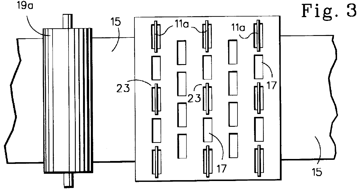
When using regularly oriented grid-type electrodes, for example, certain parts of the cathodic workpiece being coated tend to remain under portions of the grid for greater periods than other sections, and this may tend to cause differential coating thicknesses across the width of the sheet, possibly requiring additional later treatment to even out the coating thickness.
Normally, the cathodic workpiece and the
anode are maintained a fair distance apart in such lines depending upon the support of the strip to prevent touching or very close approach of the cathodic workpiece to the anode, which close approach may cause arcing with serious consequences not only to the strip, but also the the anode.
The longer an unsupported length of strip that is passed by the anode, the greater chance for substantial deviation of the strip from its pass line and possible impingement upon the anode.
However, even a multiple vertical pass line arrangement is subject to possible swaying or vibration of the strip passing between the guide rolls and the distance of the strip from the cathodic work surface is thus seldom maintained less than about one to one and a half inches from the anodes on both sides, although specialized installations having a closer gap have been used.
The coating in a continuous coating line is not usually sufficiently thick for dendritic material to begin to grow or extend from the surface.
However, as noted, in the coating of continuous black plate or strip, the coating usually is not allowed to become thick enough for any dendritic material to form.
Thus, as a thin
surface layer of electrolyte travels through the apparatus with the strip, it contacts the stationary wiper blade which is resiliently held against the strip with sufficient force to prevent it from being displaced or lifted away from the strip by the force of the electrolyte being carried or dragged along with the moving strip, but not with such force that it will not be easily lifted by the coating building up on such strip in order to prevent the coating from being damaged by the wiper blade.
Since the material of the blade is desirably rather thin in order to attain satisfactory flexibility in a
short length, such as the close spacing of the cathodic workpiece and anode surfaces demands, an orifice in the anode both large enough to provide the necessary electrolyte flow from top to bottom and vice versa, may be difficult to arrange, particularly if it must also be the correct size for maintaining a secure
interlock with the upper portions of the blade.
In addition, in the case where there is dendritic material forming upon such surface, the force of the blade should be sufficient to sever, shave off or otherwise remove such dendritic material, while at the same time not bearing upon the surface sufficiently to prevent buildup of the coating and / or to burnish or damage the coating.
The parameters of the resiliency of the blade, therefore, are essentially the generation of sufficient force, due to resiliency either of the plastic itself or of a separate resilient biasing means, to prevent any substantial escape of liquid electrolyte under the blade and to sever thin dendritic processes, if any are present, and to guide and prevent oscillation of the cathodic workpiece, but not sufficient to mar the
coated surface or to prevent the necessary buildup of an electrolytic coating of the thickness desired upon the surface.
An immovable, or non-resilient, blade would simply constrict any upward buildup of coating, a very undesirable situation.
An immovable blade would also rapidly wear.
This is somewhat more effective in immediately removing any dendritic material from the coating surface, but probably does not interchange electrolytic solution any faster, since there must be sufficient openings in the anode to allow ready back flow of solution behind the wiper blade to avoid
cavitation, which openings are then also adequate to allow flow from in front of the blade.
However, this has the
disadvantage of blocking the flow orifices in the area in which flow may be most desirable to renew the electrolytic solution.
Its main
disadvantage is that the blades are not readily replaceable without disassembling the entire structure, although, as indicated, arrangements can be made for moving slotted or otherwise appropriately constructed wiping blades to adjust them automatically or at least manually without removal of the anode from the coating solution.
Such arrangements, however, create additional complexity and the more conveniently replaced snap-in-type wiping blades shown in some previous views may be, therefore, more desirable in some operations.
However, this, in effect, slightly reduces the length of the anode section, which is undesirable.
Only one hanger can also be used at each intersection and in this case it will be desirable to bring the
flange of one anode section under the hanger and secure it to the opposite side, secure the wiping blade against this
flange of the anode and secure the
flange of the adjoining anode against the opposite side of the wiping blade, thus gaining maximum length of the anode sections, but a somewhat less secure mounting for the wiping blade, particularly when consumable electrodes are being used.
In addition, it has been found that the chevron or V-shaped wiping blades are particularly effective in preventing oscillations of the strip surface which might cause the strip to approach the closely spaced anode such that arcing between the anode and the cathodic strip surface may take place, damaging both structures.
While this arrangement is not as satisfactory as having actually flexed blades continuously biased or resiliently forced into the side of the strip at all times, it does serve to prevent the strip from touching the electrodes 315 which are positioned outboard of each of the
honeycomb sections 301.
However, because such strip surface tends to have a greater wearing effect upon the relatively
solid structure of the
honeycomb sections, rather than dissipating the force by the actual resiliency of a flexed blade or a thin flexed blade as shown in previous figures, there may be limited disadvantages in the arrangement shown in FIG. 40.
However, to some extent the multiple walls of the
honeycomb construction provides more polymeric material to wear so that the life of such wiper may not be actually that much diminished from the wear which is experienced by flexed blades.
Thus,
cavitation may become a problem directly behind the triangles or triangular configuration of the wiping blades.
If the wiping blade was, on the other hand, a solid bent blade, the shape of the blade would cause it to become essentially inflexible at and in the vicinity of the intersection of the two sections of the blade causing this section and adjoining sections to rapidly wear and interfering with the efficiency of wiping.
In view of this relationship between continuous blades and a chevron configuration, it is not practical to have a continuously renewable blade such as shown in FIGS. 32 through 36 with a strict chevron-shaped blade.
However, it has the
disadvantage of having its working or movable interengaging parts exposed to the electrolytic solution.
This arrangement provides a more even mixing in the bath on both sides, but has the drawback of inducing a flow into the small end of the space between two angled wiper blades and out of the larger end resulting in a definite tendency to have a progressively lessening flow across the strip, somewhat counterbalanced by the use of perforations in the anodes.
However, more or less uniform sized orifices can also be used.
It may be undesirable to have too acute an angle between the strip and the wiping blade because the depleted electrolytic solution, although rapidly diluted with flowing electrolytic solution, is maintained longer on or between the strip and
electrode surfaces.
However, it must be recognized that angling the resilient wiping blade more efficiently converts the movement of the strip itself into energy available to create a movement of electrolytic solution more efficiently to one side and thus, in effect, decrease the energy input required for the pump to remove, or draw the same volume of solution into the pumping
system.
Anodizing cathodes do not normally use the additional ratio of surface area of electrode over area of strip to be treated, however, and the orifices can less preferably be dispensed with, as shown in FIG. 72.
However, the mesh sections could also less desirably be rounded or arcuate in cross section.
Even large burrs on the edge of the strip or wavy strip edges might tend to jam the strip between the cathodes.
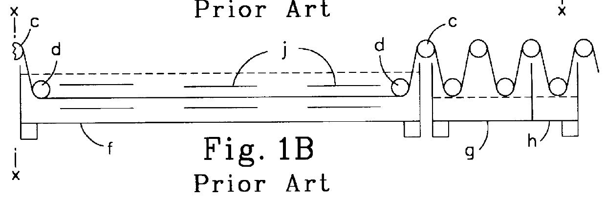
This is effective to eliminate large bubbles, but is relatively ineffective against small
oxygen bubbles that can cling to the sheet or strip by normal adhesion or capillary attraction and in the case of vertical loops or runs of strip, the guide rolls occlude significant amounts of strip surface.
In addition, while the
vertical orientation of the strip also tends to encourage the migration upwardly of an excessively heated electrolytic layer next to the strip, such tendency to rise is relatively minor.
While the collection of bubbles of
oxygen at the anodic surface is the principal difficulty with gas bubbles in anodizing, the hydrogen bubbles that gather upon the
cathode also tend to insulate the
cathode from the electrolyte, thus interfering with the achievement of
high current densities at economical power factors.
Since the blades bearing against the strip surface in FIG. 83 are, however, disposed lengthwise of the strip, the movement of the strip itself along the
processing line has little effect upon the removal of bubbles of oxygen and excessively heated electrolyte from the strip surface, although the movement of the strip along the length of the blades does induce some additional turbulence that has some beneficial effect upon the bubble situation and the temperature or depletion as the case may be of the electrolyte next to the strip surface.
However, any such effect is not great.
However, in some cases, adjacent belts may have their blades inclined in opposite directions to increase the turbulence and mixing between the belts.
Discontinuous staggered transverse blades may also be used, but have the disadvantage of not as quickly flushing the electrolyte to the side, although again, increased turbulence is attained, which, in itself, is advantageous.
It is impractical to pass the blade through side of the tank, however, because it is extremely difficult, if not impossible, to obtain a good seal and it is obviously unsatisfactory to have a leaking or dripping electrolyte tank.
While it is possible to submerge the entire coils in the tank and operate or rotate such coils from the surface, this is also usually unsatisfactory.
The overheated "
barrier layer" at the surface of the strip interferes with and in extreme cases may effectively halt electrolytic processing.
However, if, as is frequently the case, lap welded strip is run through the processing apparatus or electrolytic line, the lap welded seams frequently will catch on the flexible wiping blades tearing or otherwise damaging such blades.
However, the mesh size cannot be so large that the filter sock or bag, if used in the particular process (largely in the case of certain soluble anodes), will protrude through the mesh and catch on any irregularities on the strip such as burrs and the like and be torn or ripped off the surface of the electrodes.
Also, the open web plastic mesh cannot have mesh openings so large that irregularities in the flatness of the strip may cause close enough approach of the strip surface to the electrode surface to cause arcing between the strip and the electrodes.
In such an operation, i.e.
chromium coating process, because the plating is relatively inefficient, a large amount of hydrogen is produced by simultaneous
electrolysis of the water in the electrolyte solution, which hydrogen collects upon and coats the surface of the strip interfering with the coating operation.
In addition, depletion of the chromium content of the electrolyte occurs.
However, when the blades are used by themselves i.e. without the open-web, plastic mesh, it may be desirable to use them as close together as six inches or so and it has been found therefore, that if they are used in conjunction with open-web, plastic mesh, as shown, they can be moved significantly farther apart such as two or three feet under the same conditions with a considerable saving in cost and maintenance.
It is necessary, therefore, to either accept the decrease in plating speed with the
resultant significant decrease in production or move the anode material closer to the strip.
One difficulty with eliminating the
titanium basket or cage, as suggested as an option above, is that when the fastenings holding the individual bars or ingots to the shoes 707 dissolves in the electrolyte, the bars or ingots may then become detached from the shoes leaving one or more blank spaces in the segmented electrolytic coating roll or
cell.
The cage itself, however, also has the drawback that as the ingots, bars or nuggets dissolve, they lose volume and become loose within the cage.
Such fine crystals if allowed to grow may result in scratches upon the product and also tend in themselves to accelerate use of process energy for such undesirable thief crystals rather than the main coating.
However, as indicated, the flexible wiping blades are more subject to wear from contact with a passing strip surface.
This collection of hydrogen has a detrimental insulating effect upon the cathodes, leading to increased resistance in the circuit and contributing to
high resistance of the process requiring a
high voltage and current with a
resultant very large power requirement.
In addition, the growing
oxide layer is itself an insulating dielectric which, as electrons are driven across its thickness by the
voltage applied, rapidly heats to a high temperature so that the anodizing process is interfered with and the anodizing electrolyte adjacent the surface may even boil or vaporize into a pocketed
barrier layer essentially further insulating the surface.
In the anodizing of metals, the collection of hydrogen upon the cathodes also tends to insulate the cathodes, decreasing the efficiency of the anodizing operation.
The blade should also be resilient enough to exert a downward force sufficient to prevent the counter force of any thin surface or depletion layer of electrolyte carried along with the workpiece surface from lifting the blade from the coating surface, but not with sufficient downward force to mar the
coated surface or interfere with the buildup of a smooth, even coating.

