Energy storage and conversion apparatus

a technology of energy storage and conversion apparatus, which is applied in the direction of mechanical equipment, magnetic circuit rotating parts, shape/form/construction, etc., can solve the problems of high friction loss, complex electro-magnetic bearings, and high cos

Inactive Publication Date: 2000-11-21
KINETIC TRACTION SYST INC
View PDF26 Cites 24 Cited by
  • Summary
  • Abstract
  • Description
  • Claims
  • Application Information

AI Technical Summary

Problems solved by technology

In contrast, normal prior art energy storage and conversion apparatus use either conventional roller bearings, which result in high friction losses, or electro-magnetic bearings which are complicated, costly and potentially unreliable.

Method used


Image

  • Energy storage and conversion apparatus
  • Energy storage and conversion apparatus
  • Energy storage and conversion apparatus

Examples


Embodiment Construction

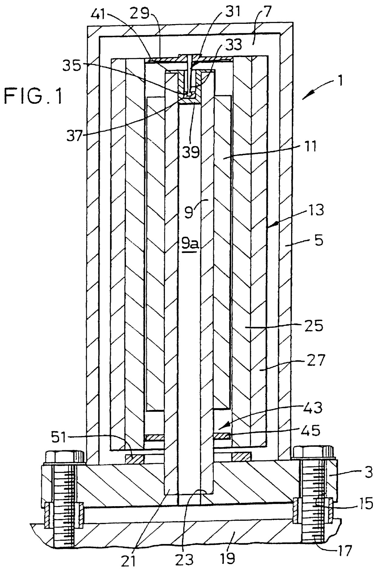
With reference to FIG. 1, an energy storage and conversion apparatus 1 comprises a base member 3, a containment 5 mounted on the base member 3 defining a vacuum chamber 7, a substantially vertical shaft 9 within the vacuum chamber 7, a stator 11, mounted on the shaft 9 and a cylindrical rotor 13 which, in use, is driven by the stator 11 to store energy as kinetic energy of the rotor 13 and acts with the stator 11 as a generator to release energy. The electrical contacts to the stator 11 (for energising the stator 11 to drive the rotor 13) are not shown in the enclosed drawings, but may pass along the hollow bore 9a of the shaft 9.

the stator 11 is not shown in any detail in FIG. 1, but may be of any appropriate type incorporating a core defining a plurality of poles, such as 4 poles, about which coils are wound to produce magnetic flux which is directed by the pole faces towards the rotor 13 to cause the rotor 13 to rotate. In this way, energy can be stored as kinetic energy of the r...


PUM


Abstract

An energy storage and conversion apparatus (1) comprising a containment (5) defining a vacuum chamber (7), a substantially vertical shaft within the vacuum chamber (7), a stator (11) on the shaft (9), and a cylindrical rotor (13) which, in use, is driven by the stator (11) to store energy as kinetic energy of the rotor (13) and acts with the stator (11) as a generator to release energy, wherein the rotor (13) is supported by the shaft (9) via an end cap (29), positioned at the upper end of the cylindrical rotor (13), which engages the shaft (9). The rotor (13) is suspended from a pin bearing (31) which is attached to an end cap (29). The pin bearing (31) sits in a bearing cup (37) mounted in a damper (39) at the end of the shaft (9). A magnet bearing (43) is provided at the lower end of the rotor (13) to assist in positioning the rotor (13) relative to the stator (11).

Description

1. Field of the InventionThis invention relates to energy storage and conversion apparatus, and in particular to an apparatus wherein a cylindrical rotor is driven by a stator within the rotor to store energy as kinetic energy of the rotor and wherein energy can be withdrawn from the rotor when the stator and rotor act as a generator.2. Discussion of Prior ArtEnergy storage and conversion apparatus of the aforementioned type have already been described in some of the present applicant's earlier patent specifications. The applicant has, however, continued to develop its energy storage and conversion apparatus and, as a result thereof, has designed an apparatus according to the present invention.According to a first aspect of the present invention, there is provided an energy storage and conversion apparatus comprisinga containment defining a vacuum chamber,a substantially vertical shaft within the vacuum chamber,a stator on the shaft, anda cylindrical rotor which, in use, is driven b...

Claims


Application Information

Patent Timeline
Patent Type & Authority Patents(United States)
IPC IPC(8): F16F15/30F16F15/315F16F15/305H02K7/09H02K5/04H02K7/00H02K7/02H02K1/27H02K16/00H02K7/08
CPCF16F15/30F16F15/305F16F15/3156H02K1/2786H02K7/025H02K7/086H02K7/09H02K16/00H02K5/04Y02E60/16H02K1/2791
Inventor HORNER, ROGER ERICTARRANT, COLIN DAVIDCROMBIE, IANBARKER, GEOFFREY MARTINHAYWARD, DAVID STEPHEN
Owner KINETIC TRACTION SYST INC
Why Eureka
Try Eureka