Apparatus and method for performing automatic control over velocity of automotive vehicle

an automatic control and vehicle technology, applied in direction finders using radio waves, instruments, reradiation, etc., can solve the problem of not being able to achieve smooth vehicular run

Inactive Publication Date: 2000-11-28
NISSAN MOTOR CO LTD
View PDF6 Cites 43 Cited by
  • Summary
  • Abstract
  • Description
  • Claims
  • Application Information

AI Technical Summary

Problems solved by technology

Consequently, a smooth vehic

Method used


Image

  • Apparatus and method for performing automatic control over velocity of automotive vehicle
  • Apparatus and method for performing automatic control over velocity of automotive vehicle
  • Apparatus and method for performing automatic control over velocity of automotive vehicle

Examples


first embodiment

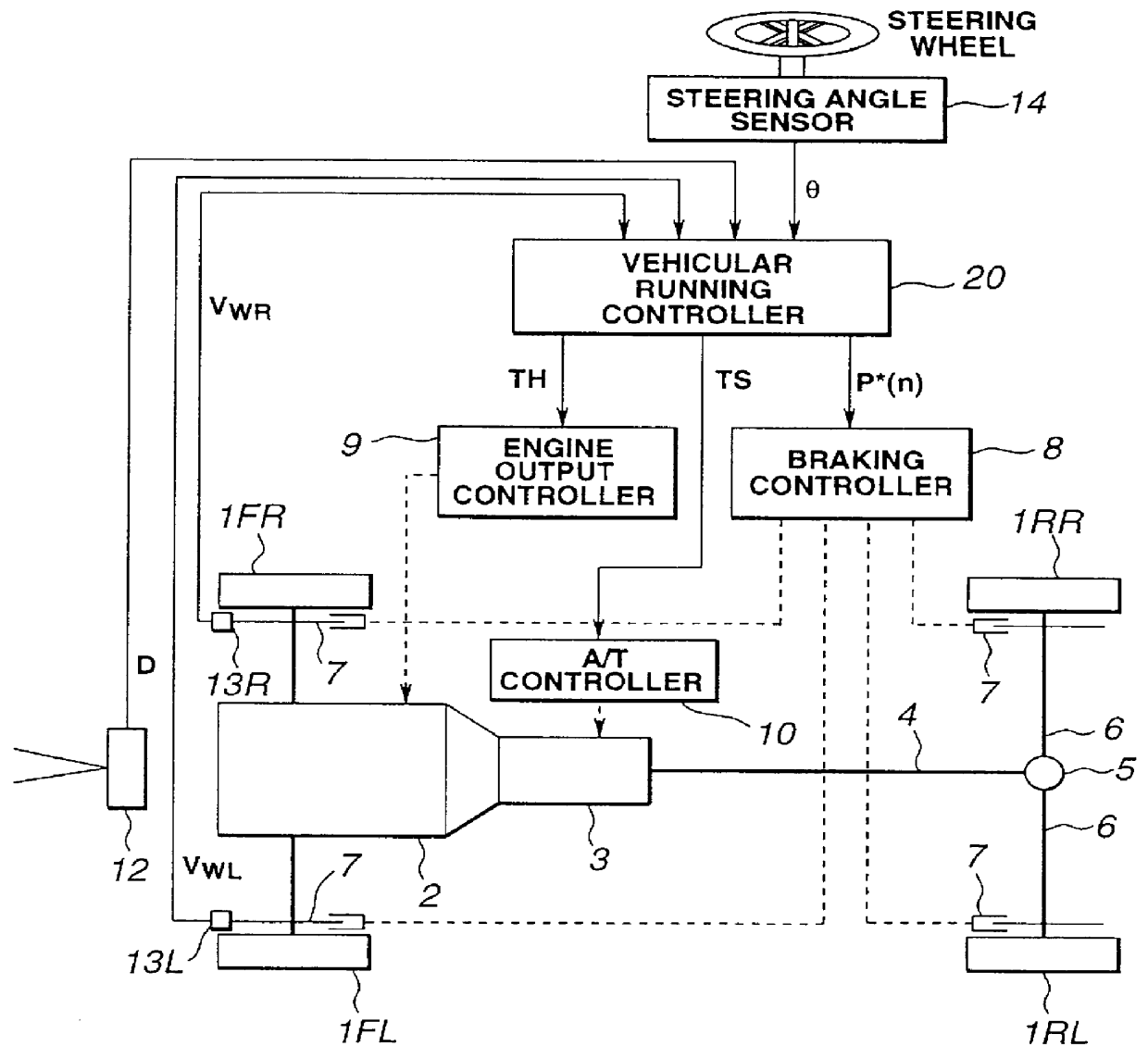
In addition, an engine output controller 9 to perform a control over an output of an engine 2 is disposed on the engine 2. A method of controlling the engine output includes a method of controlling an engine speed by adjusting an opening angle of an engine throttle valve or includes a method of controlling an engine idling speed by adjusting an idling control valve. In the first embodiment, the former method of controlling the engine speed by adjusting the throttle valve has been adopted.

Furthermore, an automatic transmission (A / T) controller 10 is disposed for controlling a gear shift position of an automatic transmission 3. The transmission controller 10 performs an up-shift or down-shift operation on the gear shift position of the automatic transmission 3 when an up or down shift command value TS from a vehicular running controller 20 as will be described later is inputted.

On the other hand, an inter-vehicle distance sensor 12 is disposed on a lower part of a vehicle body located...

second embodiment

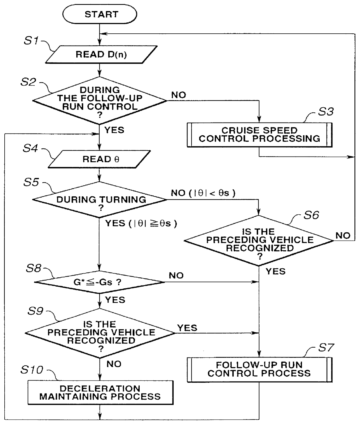
That is to say, in the second embodiment, except respective processing steps we will be described later are interposed after the step S10 in which the deceleration maintenance processing is executed, the same steps as those in FIG. 2 are provided and the explanations as those same steps will herein be omitted.

Namely, the routine goes to the step S10 to the step S21.

At the step S21, the CPU of the vehicular running controller 20 estimates the present radius of curvature R(n) of the corner for the vehicle to be passed on the basis of the present vehicular velocity V(n) and of the steering angle .theta. of the steering angle sensor 14.

At the step S22, the CPU of the controller 20 determines whether a flag FD indicating a memory-and-control on the radius of the corner is set to "1". If this control flag is reset to "0" (No) at the step S22, the CPU of the controller 20 stores the calculated radius of curvature on the corner as a radius of turn stored value R.sub.M at the step S23.

At the...

third embodiment

In the third embodiment, the deceleration is controlled according to a vehicular running situation at the time when the preceding vehicle has been recognized with the vehicular deceleration maintained.

That is to say, in the third embodiment, the steps S26 through S29 described in the second embodiment with reference to FIG. 5 are omitted as shown in FIG. 8. In place of the omitted steps S26 through S29, such a processing as deceleration control processing on the basis of the vehicular velocity as will be described below is added. It is noted that the same steps as described in FIG. 5 are processed in the third embodiment expect the addition of the new steps described above. In addition, in the third embodiment, the same processing as shown in FIG. 6 is carried out and the detailed description related to FIG. 6 will herein omitted.

In the deceleration control processing, if the result of determination at the step S25 indicates R.gtoreq.Ro, the routine returns to the step S10. If the p...


PUM


Abstract

In automatic velocity controlling apparatus and method for an automotive vehicle, an inter-vehicle distance detector is provided for detecting an inter-vehicle distance from the vehicle to another vehicle which is running at the detected inter-vehicle distance with respect to the vehicle. A vehicular running controller is provided for effecting a vehicular running control such that the vehicle follows up the other vehicle maintaining the inter-vehicle distance to the other vehicle at a predetermined inter-vehicle distance. An inter-vehicle distance determinator is provided for determining whether the inter-vehicle distance detector transfers from a first state in which the inter-vehicle distance to the other vehicle is detected to a second state in which the inter-vehicle distance to the other vehicle is undetected. A deceleration controlled state determinator is provided for determining whether the vehicle is in a deceleration controlled state when the inter-vehicle distance determinator determines that the vehicle has transferred from the first state to the second state. A deceleration keep command generator is provided for generating and outputting a vehicular deceleration keep command to the vehicular running controller to maintain a vehicular deceleration at a value which is immediately before the inter-vehicle distance determinator determines that the inter-vehicle distance detector has transferred from the first state to the second state when the deceleration controlled state determinator determines that the vehicle is in the deceleration controlled state.

Description

a) Field of the InventionThe present invention relates to apparatus and method for performing an automatic control over a velocity of an automotive vehicle in which the apparatus is mounted so as to maintain an inter-vehicle distance from the vehicle to another vehicle running ahead of the vehicle to follow up the other vehicle.b) Description of the Related ArtA Japanese Patent Application First Publication (non-examined) No. Heisei 6-206469 published on Jul. 26, 1994 exemplifies a previously proposed automatic vehicular velocity control system.In the previously proposed automatic vehicular velocity control system disclosed in the above-identified Japanese Patent Application First Publication, a radar unit is used to detect an inter-vehicle distance from the vehicle to a preceding vehicle which is running ahead of the vehicle. In a case where a variation rate of the inter-vehicle distance is equal to or below a distance variation threshold value, a variation rate of a magnitude of a...

Claims


Application Information

Patent Timeline
IPC IPC(8): B60K31/00B60T7/12B60W10/04B60W10/06B60W10/10B60W10/18B60W10/188B60W30/00B60W30/16F02D29/02G08G1/16
CPCB60K31/0008B60K31/0075B60W2720/106B60W2550/143B60W2552/20B60W2552/30B60W2050/0022
Inventor EGAWA, KENICHITANGE, SATOSHI
Owner NISSAN MOTOR CO LTD
Why Eureka
Try Eureka