Structure for and method of manufacturing aerodynamic expanded metal

a technology of expanded metal and structure, which is applied in the direction of metal/metal-oxide/metal-hydroxide catalysts, catalyst carriers, physical/chemical process catalysts, etc., can solve the problems of increasing the problem of pressure drop created by the profile of the strand

Inactive Publication Date: 2000-12-05
PRECISION COMBUSTION
View PDF5 Cites 61 Cited by
  • Summary
  • Abstract
  • Description
  • Claims
  • Application Information

AI Technical Summary

Problems solved by technology

As expanded metal is used in applications where the velocity of the fluid flow is becoming greater and greater the pressure drop created by the profile of the strand is becoming increasingly problematic.

Method used


Image

  • Structure for and method of manufacturing aerodynamic expanded metal
  • Structure for and method of manufacturing aerodynamic expanded metal
  • Structure for and method of manufacturing aerodynamic expanded metal

Examples


Embodiment Construction

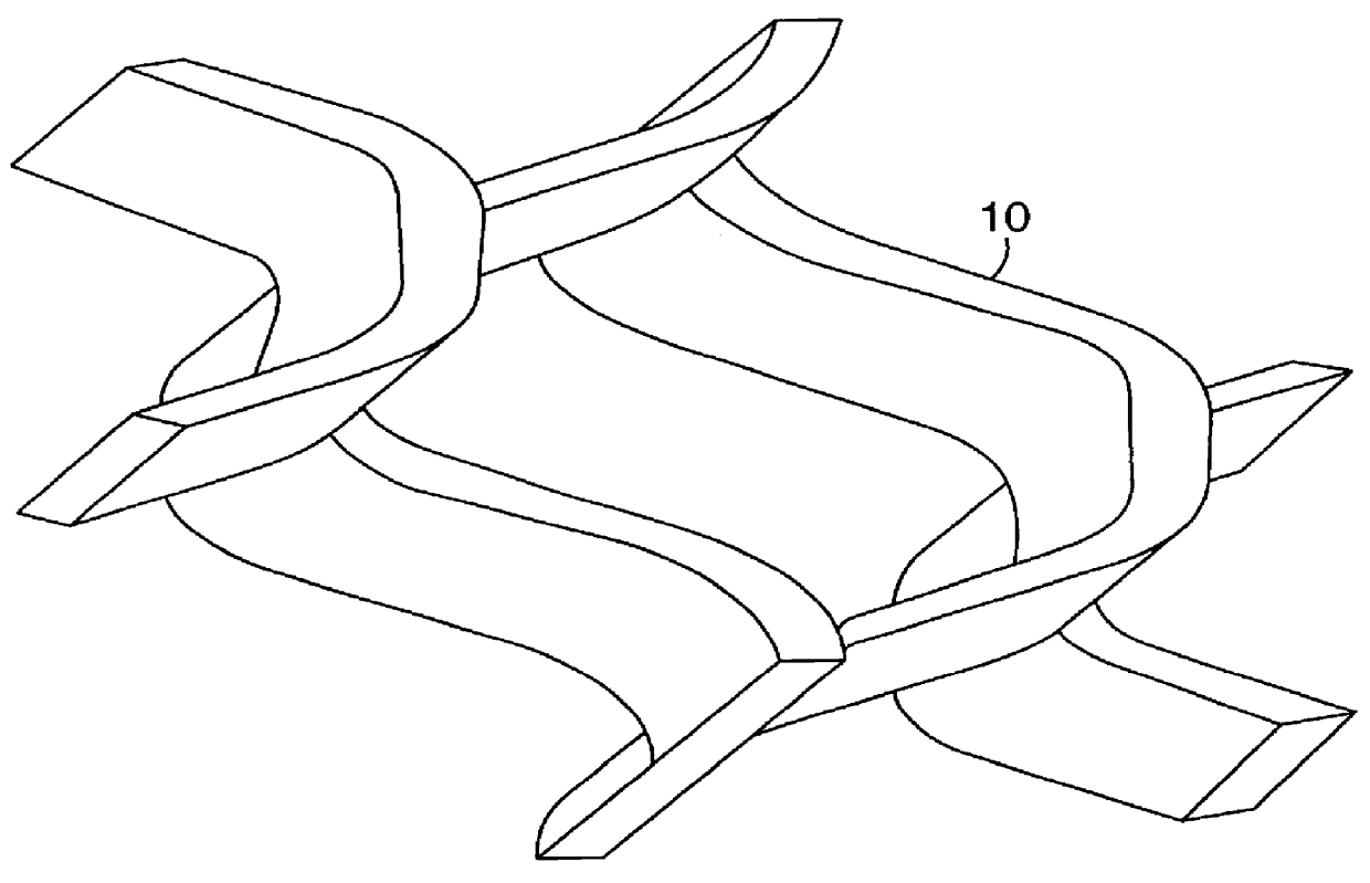
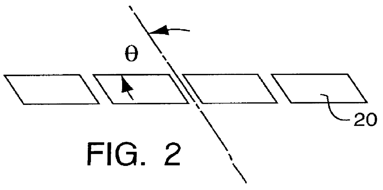
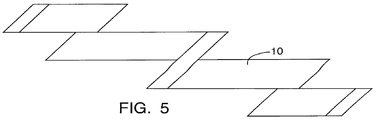
FIG. 1 is a perceptive view of an aperture defined by strands 10 in a sheet of expanded metal. The aperture is rhomboid shaped. The cross-section was formed by intermittently slitting a sheet of metal 20 at an acute angle .theta. to the surface, FIG. 2, and then stretching the metal 20 so the slit opened into the aperture. The strands 10 have a rhomboid cross-section oriented such that one acute angle of the rhomboid is positioned furthest from the place defined by the sheet.

FIG. 3 is a perspective view of an aperture with a section removed to better show the cross-section. The strand 10 has a rhomboid cross-section oriented such that one of the acute angles forms an leading edge 31 for a fluid 40 entering the aperture and the other acute angle forms a trailing edge 32 for a fluid exiting the aperture, FIG. 4. The precise acute angle is determined by the application. When this expanded metal is used in a flow stream to decrease pressure drop the acute angle should be selected to pro...


PUM

PropertyMeasurementUnit
acute angleaaaaaaaaaa
angleaaaaaaaaaa

Abstract

An expanded metal with an aerodynamic cross-section for use in high velocity fluid flows to decrease pressure drop. The expanded metal has a rhomboid cross-section with the acute angle of oriented into the flow. Also disclosed is a method of making the expanded metal.

Description

1. Field of the InventionThis invention is a structure for expanded metal that creates an aerodynamic leading edge. A method is also provided for making the structure. In one specific application, the expanded metal is used as a substrate material for a catalyst in an automotive converter.2. Brief Description of the Related ArtExpanded metal is an extremely versatile material structure. It is used in numerous applications from fascia panels, balcony railings, lawn furniture, enclosures, walkways, to supports for catalysts in automotive catalytic converters.Expanded metal comes in two basic configurations, standard and flattened. In the standard configuration, a plate of metal is cut at an angle of 90 degrees to the surface and then expanded, by pulling, to form an aperture having the ubiquitous diamond shape. The standard process leads to an expanded metal that has a rectangular strand. The flattened configuration is the standard configuration with the further processing step of col...

Claims


Application Information

Patent Timeline
Patent Type & Authority Patents(United States)
IPC IPC(8): B01J35/04B01J35/00B21D31/00B21D31/04
CPCB01J35/04B21D31/043Y10T428/12382Y10T29/18Y10T428/12361
Inventor SMITH, WARREN F.ROYCHOUDHURY, SUBINPFEFFERLE, WILLIAM C.
Owner PRECISION COMBUSTION
Why Eureka
Try Eureka