Power wrench

a power wrench and wrench technology, applied in the direction of screwdrivers, load-modifying fasteners, liquid/fluent solid measurements, etc., can solve the problems of shortening the threading operation, emitted disturbing signals, and interference by signals

Inactive Publication Date: 2000-12-19
HOHMANN JORG +1
View PDF18 Cites 116 Cited by
  • Summary
  • Abstract
  • Description
  • Claims
  • Application Information

AI Technical Summary

Problems solved by technology

Also, the measuring-technologically detected torque value depends greatly on external circumstances such as thread friction and is no precise measure for the actually reached screw pretension.
This results in a shortening of the threading operation.
Furthermore, interferences result by emission of disturbing signals or interference by signals.

Method used


Image

  • Power wrench
  • Power wrench

Examples


Embodiment Construction

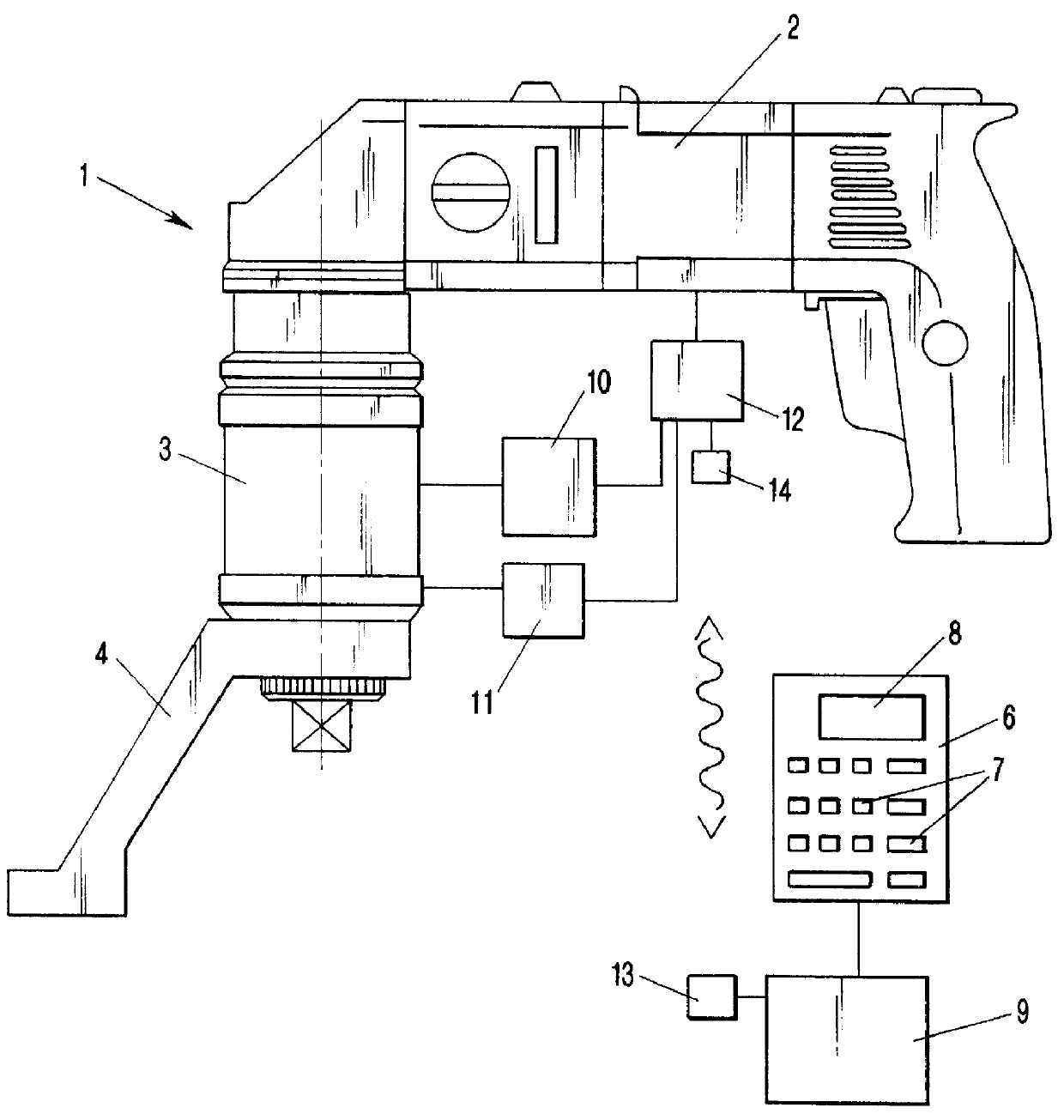
In general, the reference 1 indicates the power screwdriver having a drive unit 2 which is represented as an electric drive unit which, however, can also be operated pneumatically or hydraulically. A planetary gear system 3 is connected to the drive unit 2 which, as is shown, has an angular drive but can also extend coaxially to the main rotational axis of the drive unit. The planetary gear system 3 provides a reduction of the rpm of the drive unit 2 and increases the achievable torque.

At a neck of the planetary system 3 in the area of the square output shaft 5 of the planetary gear system 3, a support leg 4 is stationarily connected which, upon tightening of the screw, is moved against a fixed abutment and in this manner receives the reaction moment. The square shaft 5 is designed for receiving a socket wrench.

The drive unit 2 comprises an input circuit 6 which has a keyboard 7 and, optionally, a display 8 for showing the input data. With this input circuit 6, the screw size, mater...


PUM


Abstract

PCT No. PCT / EP97 / 05974 Sec. 371 Date Jul. 16, 1999 Sec. 102(e) Date Jul. 16, 1999 PCT Filed Oct. 29, 1997 PCT Pub. No. WO98 / 22263 PCT Pub. Date May 28, 1998A power screwdriver has a drive unit and an input circuit for inputting screw size, material quality, pitch, and clamping length of a screw. An evaluation circuit is provided for determining a nominal prestress force based on input screw size, material quality, and clamping length, for determining a nominal torque based on the nominal prestress force and the pitch, and for determining the screw clamping angle resulting from the nominal prestress force and the pitch. A sensing device for sensing the actual torque is provided, and a further sensing device for sensing the actual screw clamping angle is present. A control and switch-off device controls further rotation of the drive unit when the actual torque coincides with the nominal torque and switches off the drive unit when the actual screw clamping angle coincides with the nominal screw clamping angle. The nominal torque, based on which the additional rotation o f the drive unit is controlled until the nominal screw clamping angle is reached, is set to a value which is smaller than the torque corresponding to the nominal pretension force. An additional rotation angle of the drive unit, for reaching the nominal screw clamping angle corresponding to the nominal prestress force, is determined based on the difference between the nominal screw clamping angle and the adjusted screw clamping angle corresponding to the preset nominal torque and is used for switching off the drive unit.

Description

BACKGROUND OF THE PRIOR ARTThe invention relates to a power screwdriver with a drive unit, a sensing device for the actual torque as well as optionally for the actual screw clamping angle, and an electronic control of the revolutions per minute and / or the torque and / or the screw clamping angle.In German patent 43 07 131 a power screwdriver is disclosed having a drive unit having a with planetary gear downstream thereof, a torque detection at the drive shaft, an evaluation electronic circuit, and a switch-off device for the drive unit, a sensing device for detecting the rotational position of the drive unit whereby the switch-off device has a adjustable preset device for a certain torque determined by the torque detection device, and additionally an adjustable preset device, for a certain follower path determined by the rotational position detection device and wherein switching off of the drive unit after reaching the preset torque is carried out followed by a further rotation by an ...

Claims


Application Information

Patent Timeline
Patent Type & Authority Patents(United States)
IPC IPC(8): B25B23/14B23P19/00B23P19/06B25B23/151
CPCB23P19/066B25B23/14B23P19/102
Inventor HOHMANN, JORGHOHMANN, FRANK
Owner HOHMANN JORG
Why Eureka
Try Eureka