Loop antenna device

a technology of loop antenna and loop antenna, which is applied in the direction of antennas, differentially interacting antenna combinations, polarised antenna unit combinations, etc., can solve the problems of complex structure of large loop antenna devices per se, and difficult miniaturization of loop antennas per s

Inactive Publication Date: 2000-12-19
AISIN SEIKI KK
View PDF3 Cites 57 Cited by
  • Summary
  • Abstract
  • Description
  • Claims
  • Application Information

AI Technical Summary

Problems solved by technology

This requires a fixing means for each antenna, resulting in that the structure of the loop antenna device per se becomes complex.
In addition, dead spaces are defined between the ferrite bar B and the circular coil Li by which a miniaturization of the loop antenna per se gets difficult.
In the latter conventional loop antenna device wherein both loop antennas cross at right angles, devices such as an a R-C circuit and transformer for establishing a phase difference of 90 degrees between magnetic components generated at both loop antennas are required, resulting in that the loop antenna device per se becomes large and complex in structure.

Method used


Image

  • Loop antenna device
  • Loop antenna device
  • Loop antenna device

Examples


Embodiment Construction

Preferred embodiments of the present invention will be described hereinafter in detail with reference to the accompanying drawings.

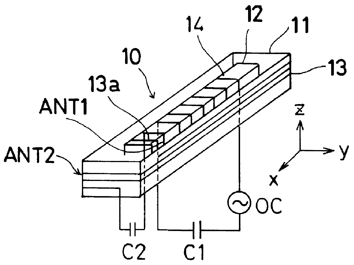
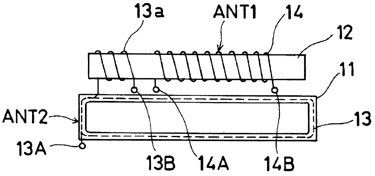
Referring first to FIGS. 1 (A) through 3, a loop antenna device 10 includes a first antenna ANT1 and a second antenna ANT2. The first antenna ANT1 is constructed such that a first coil 14 formed of a good electric conductive material such as cooper is wound around a thin rectangular prism ferrite member 12 which is Mn-Zn family or Ni-Zn family material for increasing antenna efficiency. The ferrite member 12 can be formed into a thin round prism configuration.

The second antenna ANT2 is so configured as to be a closed rectangular loop member having at its center portion a rectangular opening in which the ferrite member 12 is placed such that a clearance is defined therebetween. The second antenna ANT2, which is similar to the ferrite member 12 in shape, is configured such that a second coil 13 formed of a good electric conductive material is wound around ...


PUM


Abstract

A loop antenna has a first antenna generating a first magnetic field and a second antenna generating a second magnetic field such that the first magnetic field and the second magnetic field each have a different axis. A serial resonant circuit and a parallel resonant circuit are provided for the first antenna and the second antenna, respectively. The serial resonant circuit has a ferrite member, a first coil wound around the ferrite member, a resonant capacitor, and a power source connected thereto in series. The in-series connection of the resonant capacitor and the power source are connected across the first coil. The parallel resonant circuit has a link coil wound around the ferrite member, a second coil connected to the link coil in series and wound around a member outside the ferrite member, and a resonant capacitor connected in parallel to the series connection of the second coil and the link coil.

Description

1. Field of the InventionThe present invention is directed to a loop antenna device which generates two different magnetic fields, and in particular to the structural improvement of a loop antenna which has two antennas for generating thereat two different or orthogonal magnetic components, respectively.2. Related Prior ArtOne of the conventional loop antenna devices is disclosed in German Patent Publication DE 4105826. The conventional loop antenna device includes a first antenna A1 and a second antenna A2. The first antenna A1 has a coil L2 wound around a ferrite rod or bar B and a resonant capacitor C2 connected thereto in parallel which constitutes a parallel resonant circuit. The second antenna A2 has a circular coil L1 accommodating therein the ferrite bar B and a resonant capacitor C1 connected in parallel to the circular coil L1 which constitutes a parallel resonant circuit. The ferrite bar B is also wound with a coil L3 to which an amount of current is fed from a power sour...

Claims


Application Information

Patent Timeline
Patent Type & Authority Patents(United States)
IPC IPC(8): H01Q21/29H01Q7/08H01Q21/00H01Q7/00H01Q21/24H01Q25/00
CPCH01Q7/08H01Q21/29H01Q21/24
Inventor MURAKAMI, YUICHIMUSHIAKE, EIJIHATANO, RIKUOAOKI, KOJI
Owner AISIN SEIKI KK
Why Eureka
Try Eureka