Hybrid-switching Step-down Converter with a Hybrid Transformer

a hybrid transformer and converter technology, applied in the direction of electric variable regulation, process and machine control, instruments, etc., can solve the problems of small leakage inductance, and achieve the effect of increasing the number of turns, increasing the magnetics size, and increasing the magnetic loss

Active Publication Date: 2012-10-04
CUKS
View PDF7 Cites 55 Cited by
  • Summary
  • Abstract
  • Description
  • Claims
  • Application Information

AI Technical Summary

Benefits of technology

[0011]The main objective is to provide an alternative to the present buck converter and tapped inductor buck converter to provide the converter with large step-down conversion ratios needed, such as 24:1 and achieve that with much improved efficiency while providing simultaneously magnetic size reductions and a fast transient response. This is achieved by providing step-down converter with a hybrid transformer, which in addition to inductive energy transfer of tapped-inductor buck converter, provides a simultaneous transfer of the resonant capacitor discharge current to the load via the same two winding magnetic structure but now operating as a true ac transformer during the OFF-time interval, hence the proposed name hybrid transformer. Both energy transfer mechanisms provide the increased total current to the load at any duty ratio thereby increasing voltage step-down significantly.

Problems solved by technology

Even a small leakage inductance was a big problem in the prior-art tapped-inductor buck converter.

Method used


Image

  • Hybrid-switching Step-down Converter with a Hybrid Transformer
  • Hybrid-switching Step-down Converter with a Hybrid Transformer
  • Hybrid-switching Step-down Converter with a Hybrid Transformer

Examples


Embodiment Construction

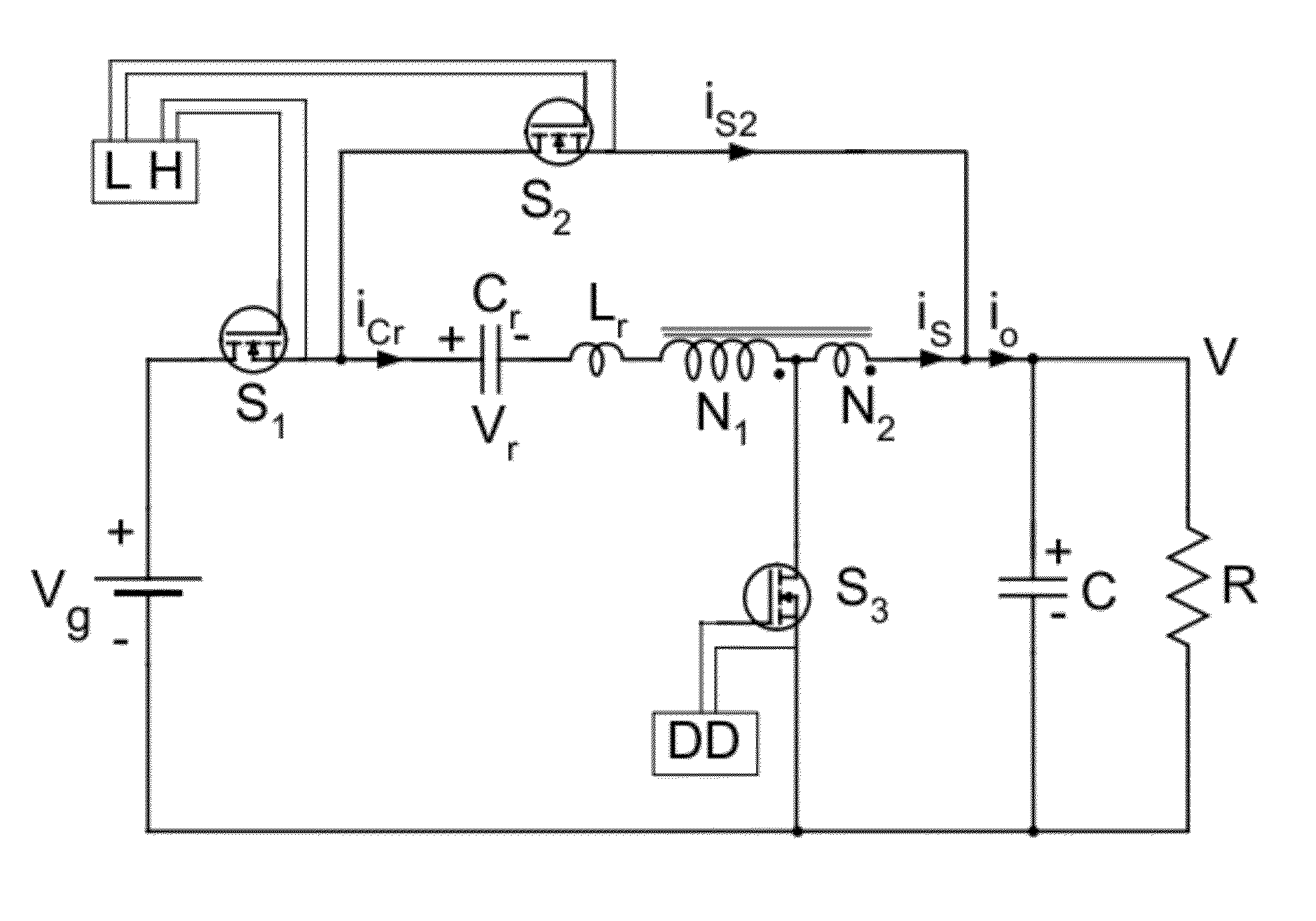
[0183]An alternative converter topology could be obtained by connecting the second switch S2 of the basic converter in FIG. 6a to the ground instead of to the output terminal to result in another converter embodiment shown in FIG. 25a. This configuration has a disadvantage that the resonant current does not directly contribute to the load as in previous case, but does keep the same contribution through the hybrid transformer. The implementation of converter in FIG. 25a with all MOSFET transistors is shown in FIG. 25b. This practical implementation shows additional advantages:

a) simple drive for S1 and S2 switches using the high-side driver and direct drive for synchronous rectifier switch S3.

b) protection of the load from switch S1 failing short and staying in short condition.

[0184]Those skilled in the art could also find other beneficial placements of the resonant inductor, which would also employ above combined inductive and capacitive energy storage and transfer which is the main...


PUM


Abstract

The present invention employs a resonant inductor, a resonant capacitor and a hybrid transformer using a Hybrid-switching method with three switches which results in two distinct switched-networks: one for ON-time interval and another for OFF-time interval. Resonant inductor is placed in series with the hybrid transformer primary to insure the continuity of primary and secondary currents at the switching transitions. The hybrid transformer converts both inductive and capacitive energy storage from the source to the load. The two-phase extension results in tenfold reduction of the output current ripple.Despite the presence of the resonant inductor current during the OFF-time interval, the output voltage is neither dependent on resonant component values nor on the load current but depends on duty ratio D and turns ratio n of the hybrid transformer only. Thus a simple regulation of output voltage is achieved using duty ratio D control.

Description

FIELD OF THE INVENTION[0001]The non-isolated switching DC-to-DC converters can be broadly divided into three basic categories based on their input to output DC voltage conversion characteristics: a) step-down only (buck converter), step-up only (boost converter) and step-down / step-up such as flyback, SEPIC, and Ćuk converters (1,2). This invention relates to the step-down class of switching DC-to-DC power converters such as buck converter.[0002]Many Point of Load Applications (POL) and Voltage Regulator Modules (VRM's) require a rather large step-down conversion ratios, such as 12:1 or even 24:1 to convert the standard 12V input voltage to 1V or 0.5V output regulated voltage required by the modern microprocessors and other electronic loads. This invention also relates to this particular subset of the step-down converters. However, it is equally applicable to a broader class of other moderate to high step-down voltage conversions.[0003]Classifications of currently known switching con...

Claims


Application Information

Patent Timeline
Patent Type & Authority Applications(United States)
IPC IPC(8): G05F1/618H02M1/00
CPCH02M3/158Y02B70/1425Y02B70/10H02M3/1588H02M3/1584H02M1/0054H02M3/1586H02M3/01H02M3/005
Inventor CUK, SLOBODAN
Owner CUKS
Why Eureka
Try Eureka