Position indicator, variable capacitor, position input device and computer system

a technology of position indicators and capacitors, which is applied in the direction of variable capacitors, resistance/reactance/impedence, instruments, etc., can solve the problems of increasing manufacturing costs and difficulty in reducing the outer diameter of variable capacitors, so as to reduce the initial capacitance of variable capacitors, simplify the configuration of variable capacitors, and reduce the radial dimension of position indicators

Inactive Publication Date: 2009-03-19
WACOM CO LTD
View PDF5 Cites 55 Cited by
  • Summary
  • Abstract
  • Description
  • Claims
  • Application Information

AI Technical Summary

Benefits of technology

[0022]According to the present invention, the configuration of the variable capacitor can be simplified so as to reduce the radial dimension of the position indicator, and reduce the initial cap...

Problems solved by technology

Further, since a double-housing is used in the variable capacitor disclosed in Japanese Patent No. 3150685 (refer to FIG. 2 of Japanese Patent No. 3150685), i...

Method used


Image

  • Position indicator, variable capacitor, position input device and computer system
  • Position indicator, variable capacitor, position input device and computer system
  • Position indicator, variable capacitor, position input device and computer system

Examples


first embodiment

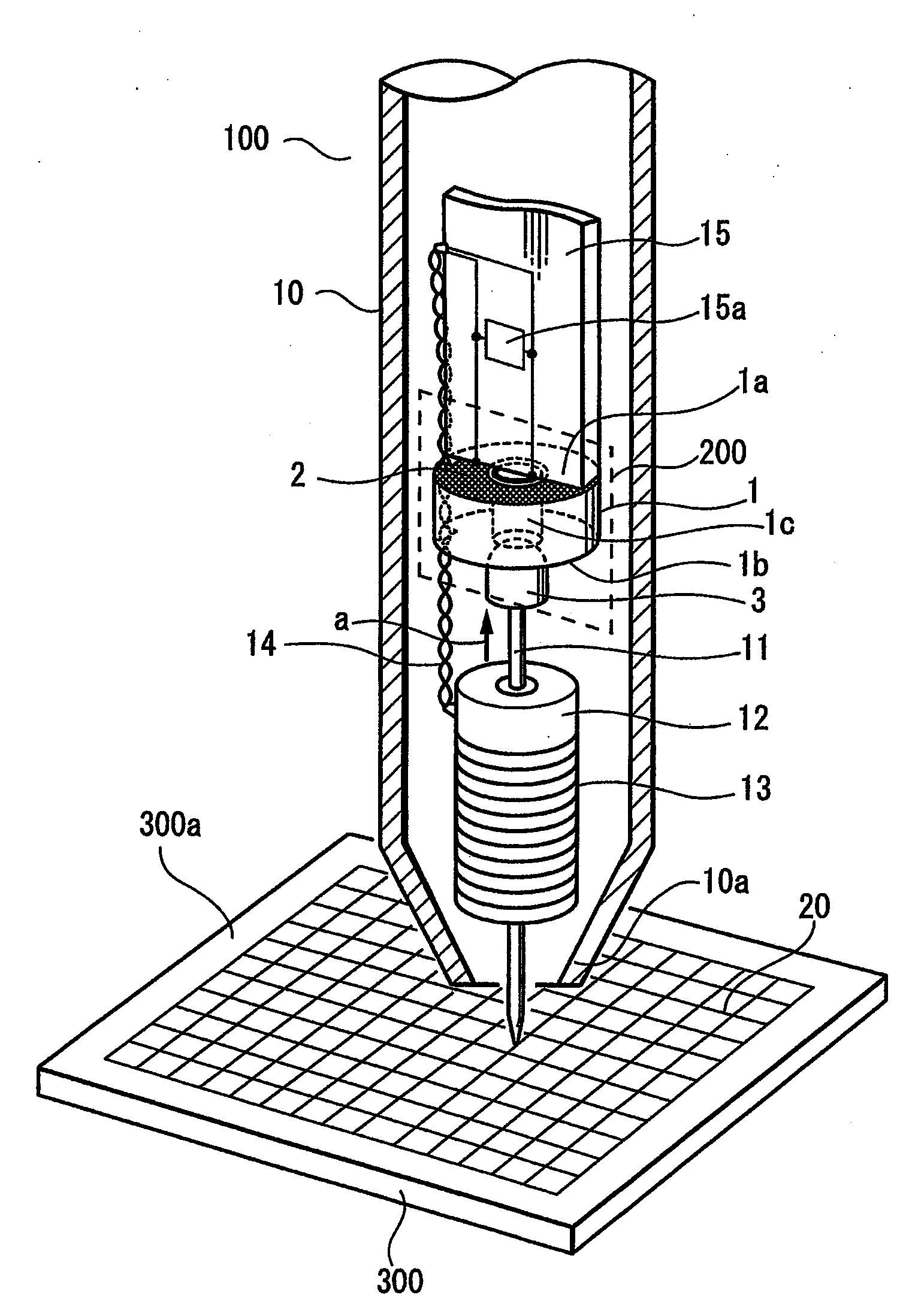
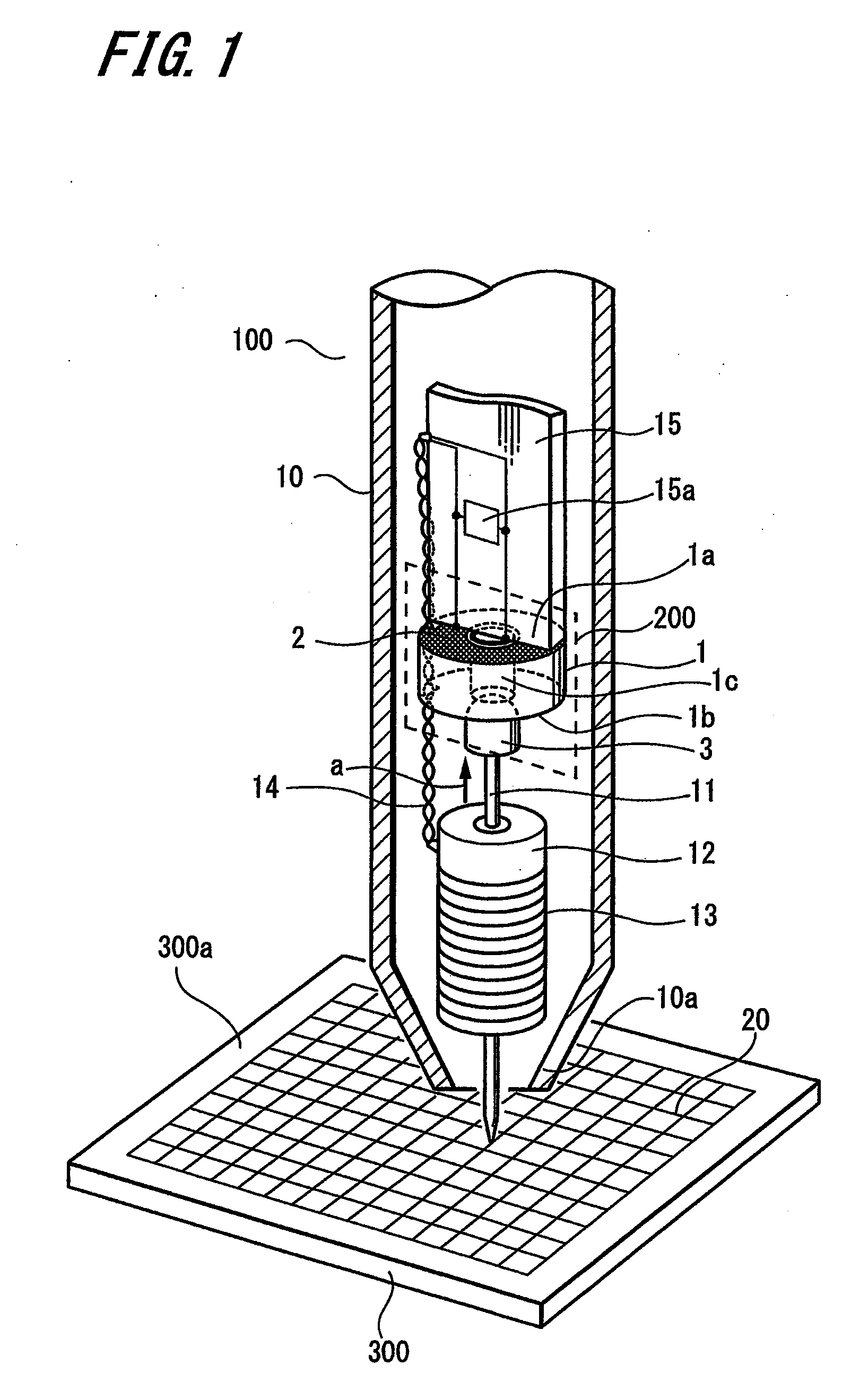
[0033]the present invention will be described below with reference to FIGS. 1 to 8. Firstly, a configuration of an exemplary embodiment of a position indicator including a variable capacitor, and a position input device, according to the present invention, will be described below with reference to FIG. 1.

[0034]The position input device includes a position indicator 100 and a tablet 300. The position indicator 100 is used at a position facing an upper surface 300a of the tablet 300. The tablet 300 is enabled to be connected to a personal computer (not shown). The tablet 300 detects the coordinates of a position indicated by the position indicator 100 and transmits the detected position coordinates to the personal computer. Based on the position coordinates transmitted from the tablet 300, the personal computer performs an input operation, such as a hand-drawn illustration input operation and / or a handwritten character input operation, with various software installed in the personal c...

second embodiment

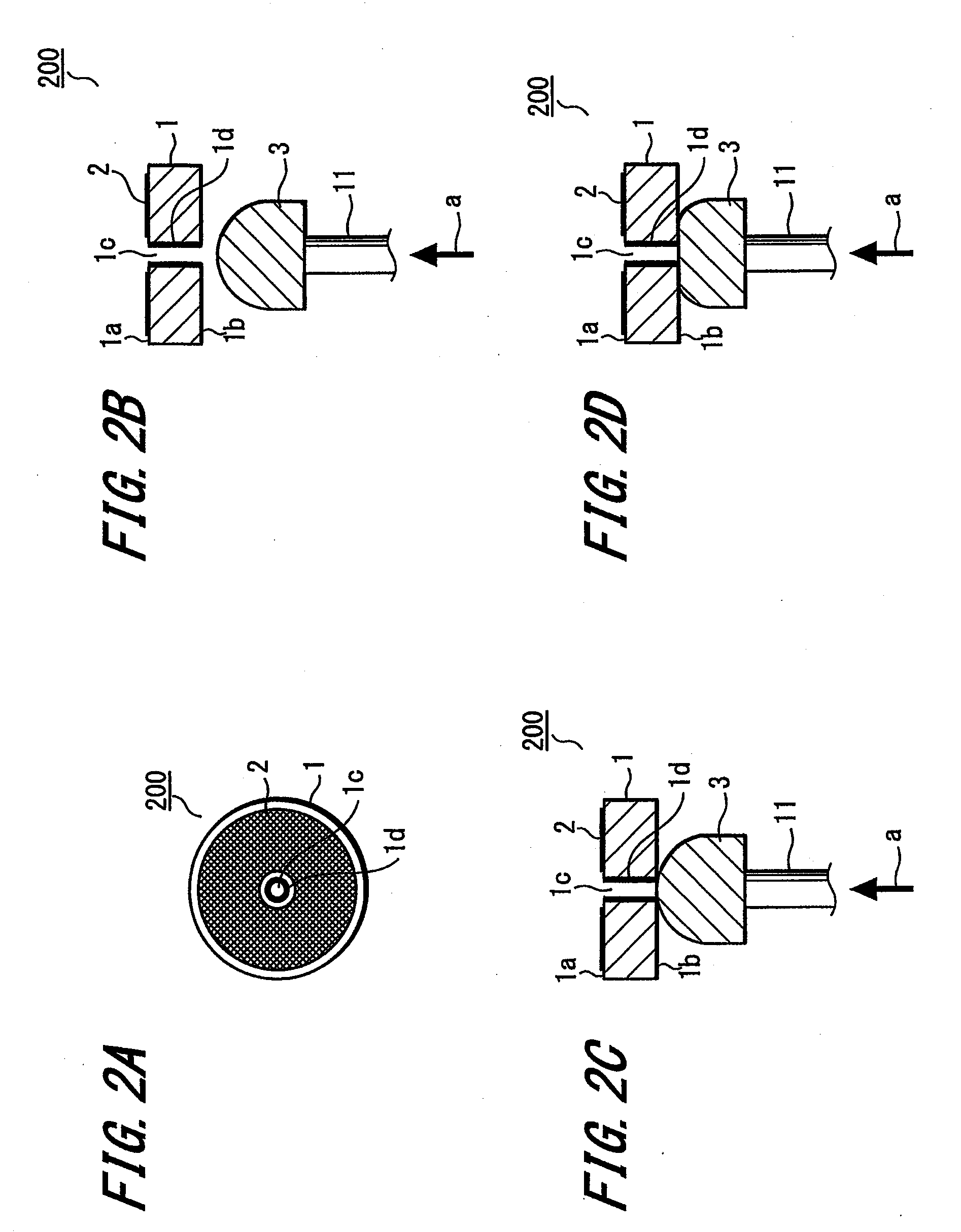
[0087]A configuration of a variable capacitor according to the present invention will be described below with reference to FIG. 9. FIG. 9 is a cross section showing the variable capacitor. In FIG. 9, components identical to those in FIGS. 2A to 2D are denoted by the same reference numerals as in FIGS. 2A to 2D, and detailed explanations thereof will be omitted.

[0088]According to the second embodiment, a conductive pin 41 is inserted into the hole 1c of the dielectric 1, instead of the conductive layer 1d provided on the inner wall of the hole 1c. When the conductive pin 41 contacts the conductive elastic member 3, the conductive elastic member 3 is brought into electrical connection with the resonant circuit via the conductive pin 41. One end of the conductive pin 41 in the longitudinal direction is provided with a pin head portion 42. A stepped portion 43 is formed on the lower surface 1b of the dielectric 1. The stepped portion 43 is a recessed portion recessed around the hole 1c....


PUM


Abstract

A position indicator (100) has a variable capacitor 200, a resonant circuit (36) configured with a position indicating coil (13) and a resonant capacitor (15a), and a rod (11). The variable capacitor (200) has a flat disc-shaped dielectric (1) having two mutually opposite surfaces (1a, 1b), an electrode (2) provided on one surface (1a) of the dielectric (1), a hole (1c) extending between the two mutually opposite surfaces of the dielectric, a conductive portion electrically connecting both ends of the hole, and a conductive elastic member (3) provided near the other surface (1b) of the dielectric (1). The conductive elastic member (3) is arranged on one end of the rod (11). When a pen pressure in the direction of arrow “a” is applied to the other end of the rod (11), the conductive elastic member (3) is pressed against the dielectric (1) so as to be flattened, and the capacitance of the variable capacitor (200) changes in response to the change in the contact area between the conductive elastic member (3) and the dielectric (1).

Description

CROSS REFERENCES TO RELATED APPLICATIONS[0001]The present application claims priority under 35 U.S.C. § 119 from Japanese Patent Application JP 2007-241256 filed in the Japanese Patent Office on Sep. 18, 2007, the entire contents of which is incorporated herein by reference.BACKGROUND OF THE INVENTION[0002]1. Field of the Invention[0003]The present invention relates to a position indicator for use with a digitizer adapted to input position information, a variable capacitor suitably used in the position indicator, a position input device including the position indicator and a digitizer, and a computer system using the position input device, particularly in which the structure of the variable capacitor used in a pen pressure detecting section of the position indicator is simplified and therefore the radial dimension of the position indicator is reduced.[0004]2. Description of the Related Art[0005]A variable capacitor is conventionally used in a pen pressure detecting section of a posi...

Claims


Application Information

Patent Timeline
IPC IPC(8): G06F15/00H01G5/00G01R27/26
CPCG06F3/046G06F3/03545G06F3/0445
Inventor FUKUSHIMA, YASUYUKIFUJITSUKA, HIROYUKI
Owner WACOM CO LTD
Why Eureka
Try Eureka