Series resonant converter

a series resonant converter and series resonant technology, applied in the direction of electric variable regulation, process and machine control, instruments, etc., can solve the problems of unnecessary circuit loss power loss and noise generation, etc., to prevent the occurrence of recovery current and reduce power loss.

Active Publication Date: 2009-11-26
ORIGIN CO LTD
View PDF15 Cites 54 Cited by
  • Summary
  • Abstract
  • Description
  • Claims
  • Application Information

AI Technical Summary

Benefits of technology

[0011]By configuring in the abovementioned circuit structure, the first switching device and the second switching device alternately turn on and off, and the inverter circuit converts DC power supply inputted from the input terminal and supplies alternating voltage to the output terminal via the transformer. The unidirectional device unit (a first unidirectional device and a second unidirectional device) prevents electric charge of a resonant capacitor unit (a first resonant capacitor and a second resonant capacitor) from being discharged to a primary side of a transformer. Thus, current is prevented from being returned to the output terminal side from a resonant capacitor unit.
[0012]Furthermore, as a preferable circuit for preventing the occurrence of recovery current and reducing power loss, a inverter circuit of a series resonant converter according to the present invention includes a first feedback diode arranged in parallel with a first switching device and having a reversed polarity that is opposite to that of a first switching device, and a second feedback diode arranged in parallel with a second switching device and having a reversed polarity that is opposite to that of a second switching device.

Problems solved by technology

However, in such a series resonant converter, it has been suggested that there is power loss caused by energy of a resonant circuit returning to the DC power supply via a feedback diode connected in parallel with the switching device.
In other words, a feedback current to the DC power supply improves power efficiency in that it returns the energy to the DC power supply, but the energy supplied from the DC power supply to the resonant circuit is returned to the DC current, which causes unnecessary loss of circuit caused by the current which has not been supplied to a load device.
Therefore, at the moment when the other switching device turns on, reverse voltage is applied to the feedback diode flowing feedback current, and precipitous recovery current (reverse recovery current) flows in a recovering time until a reverse direction blocking characteristics of the feedback diode is recovered, which generates power loss and noise.
Therefore, current which is not supplied to a load device becomes large, which generates unnecessary circuit loss.
In addition, in every half-cycle time of a switching cycle of a switching device, since recovery current flowing in a reverse direction is generated at a feedback diode, not only power loss of a feedback diode is increased, but also unnecessary turn-on power loss is generated in a switching device in an amount as much as the recovery current flowing, thereby reducing power efficiency of a resonant converter.
Moreover, since such recovery current has a sharp waveform, it has a deficiency in generating noise even if its current waveform is rendered to be a sine wave form by resonance.

Method used


Image

  • Series resonant converter
  • Series resonant converter
  • Series resonant converter

Examples


first embodiment

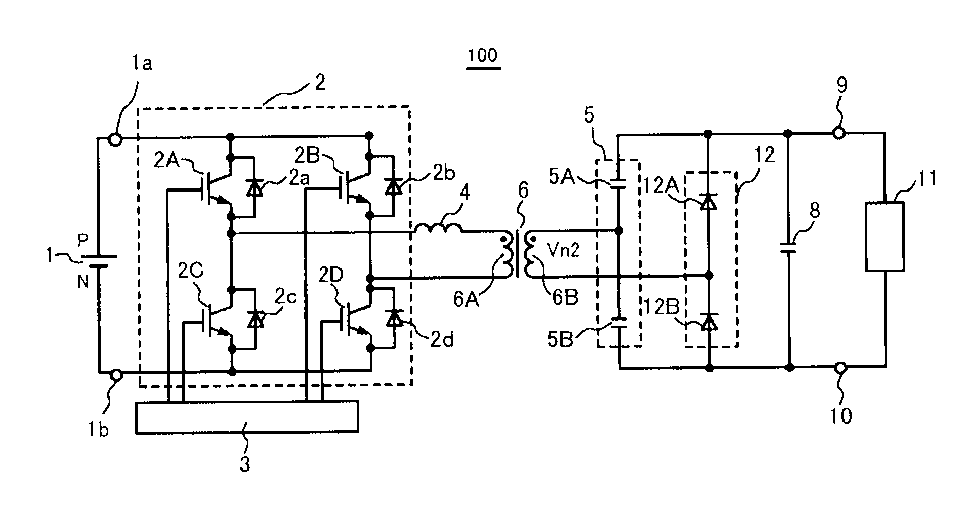
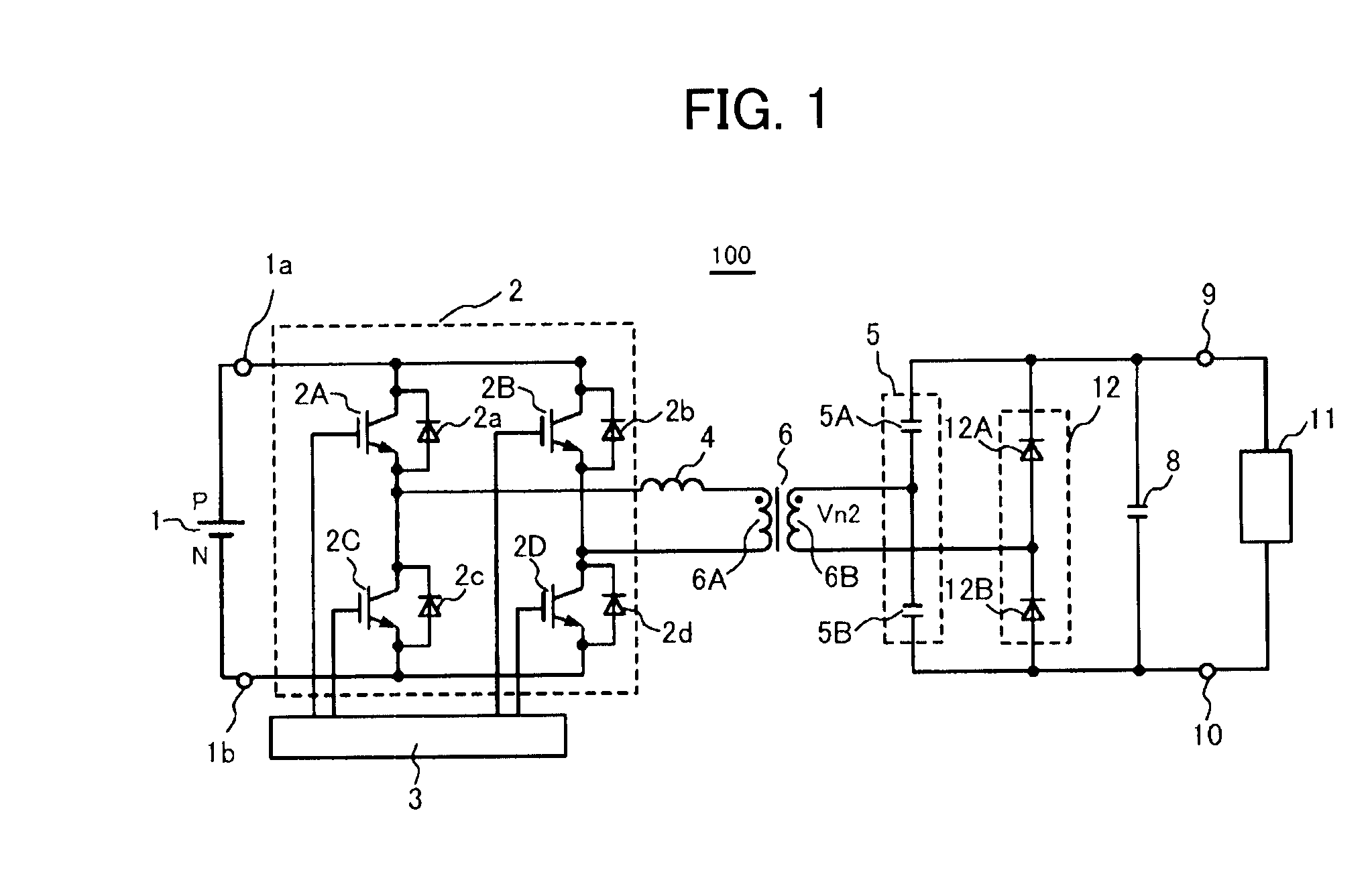
[0027]A series resonant converter according to a first embodiment of the present invention is described with reference to FIGS. 1 to 4. FIG. 1 shows a circuit structure of a first series resonance type converter 100 of the present invention. The series resonant converter 100 includes a DC power supply 1, an inverter circuit 2, a control circuit 3, a resonant inductor 4, a resonant capacitor unit 5, a transformer 6 having a primary winding 6A and a secondary winding 6B, a unidirectional device unit 12, a smoothing capacitor 8, and output terminals 9 and 10. The primary winding 6A of the transformer 6 is connected to an inverter circuit 2 side via the resonant inductor 4, which is connected in series. One end of the secondary winding 6B of the transformer 6 is connected to the resonant capacitor unit 5 side and the other end of the secondary winding 6B is connected to the unidirectional device unit 12 side. A load 11 such as a common installation device including a vacuum device and a...

second embodiment

[0075]Next, a series resonant converter 200 according to the second embodiment of the present invention shown in FIG. 5 is described. A point of difference between the second series resonant converter 200 and the first series resonant converter 100 is that a reverse charge control diode 31 is connected in parallel with the first resonant capacitor 5A and a reverse charge control diode 32 is connected in parallel with the second resonant capacitor 5B.

[0076]Furthermore, the transformer 6 is a leakage transformer 6 including a leakage inductor 6C without the resonant inductor 4 shown in FIG. 1. That is, in the second embodiment, the leakage inductance 6C of the transformer 6 gives the overall inductance L of the resonant induction device necessary for series resonance. Since the leakage transformer 6 is a combination of the resonant inductor 4 and the transformer 6 in FIG. 1 in principle and is functionally the same as the first series resonant converter shown in FIG. 1, main operation...

third embodiment

[0084]Next, a series resonant converter 300 according to the third embodiment is described in FIG. 6. A normal half-bridge inverter circuit 2 is used in the series resonant converter 300. It is a half-bridge inverter circuit including a switching device arm connected in series with the two switching devices 2A and 2C, respectively.

[0085]In the half-bridge inverter circuit 2, a capacitor 2X is used instead of the switching device 2B and the feedback diodes 2b, and a capacitor 2Y is used instead of the switching device 2D and the feedback diode 2d of the full-bridge inverter circuit 2 in FIG. 1 or 5. Since an inverter circuit with fewer switching devices, as compared to the full-bridge inverter circuit, can be used, simplified control of the switching device can be made.

[0086]In the series resonant converter 300, a field-effect transistor (hereinafter referred to as FET) is used as the unidirectional device unit 12. The unidirectional device unit 12 is configured with a so-called sync...


PUM


Abstract

A series resonant converter of the present invention includes an inverter circuit having at least a pair of a first and second switching device connected between two input terminals, a transformer having a primary winding and a secondary winding connected to the inverter circuit, a first and second resonant capacitor connected to a secondary side of the transformer and connected in series to each other between two output terminals, a first and second unidirectional device connected in series to each other, and a resonant induction device that is operated along with the first and second resonant capacitor and resonates in series. The first and second unidirectional device are configured such that current does not flow from the first and second resonant capacitor to the input terminal by preventing electric charge of the first and second resonant capacitor from being discharged to a primary side of the transformer.

Description

CROSS-REFERENCE TO RELATED APPLICATIONS[0001]The present application claims the benefit of Japanese Patent Application No. 2008-135357, filed on May 23, 2008 and Japanese Patent Application No. 2008-181886, filed on Jul. 11, 2008, the subject matters of which are hereby incorporated herein by reference in their entirety.FIELD OF THE INVENTION[0002]The present invention relates to a series resonant converter which uses series resonant effect of inductance and capacitance.BACKGROUND OF THE INVENTION[0003]A series resonant converter using series resonance of an inductance of a resonance inductor and a capacitor of a resonant capacitor is commonly used as a converter with high power conversion efficiency. A series resonant converter is mainly divided into a current mode series resonant converter in which a resonant capacitor is connected in series with a primary winding or a secondary winding of a transformer and a voltage mode series resonant converter in which a resonant capacitor is ...

Claims


Application Information

Patent Timeline
Patent Type & Authority Applications(United States)
IPC IPC(8): H02M3/335
CPCH02M3/337Y02B70/1491H02M2001/0058Y02B70/1433Y02B70/10Y02P80/10H02M1/0058H02M3/33573H02M3/33571H02M3/01
Inventor UENO, SHINGOSAITO, ATSUSHIWATANABE, KIYOMI
Owner ORIGIN CO LTD
Why Eureka
Try Eureka