Method of regulating the vacuum level in a milking apparatus, and a milking apparatus

a technology of vacuum level and milking apparatus, which is applied in the direction of milking devices, axial flow pumps, fluid engines without positive displacement, etc., can solve the problems of inability to adjust the vacuum level, the replacement pump normally consumes more energy than necessary,

Inactive Publication Date: 2000-12-26
DELAVAL HLDG AB
View PDF17 Cites 34 Cited by
  • Summary
  • Abstract
  • Description
  • Claims
  • Application Information

AI Technical Summary

Benefits of technology

A dynamic vacuum pump can be designed in such a manner that the effect supply, at least within a certain flow interval, is reduced with a decreasing flow through the vacuum pump, whereas the pressure ratio remains essentially constant within this flow interval. Thus, by choosing such a dynamic vacuum pump for a milking apparatus, the possibilities to regulate the vacuum level of the milking apparatus may be improved. Preferably, this regulation may be performed by, for instance, a slight increase of the pressure ratio between the outlet and the inlet, e.g. by throttling the inlet, such that the flow through the vacuum pump will decrease and the effect supplied is reduced, resulting in a lower energy consumption.
According to another embodiment, the size of the flow may be regulated by controlling the direction of the flow at the inlet of the vacuum pump. This may be realized by means of guide blades. The latter embodiment results in a greater effect reduction since the pressure ratio across the vacuum pump is smaller.

Problems solved by technology

A disadvantage of this conventional way of regulating the vacuum level is that the deplacement pump normally consumes more energy than necessary since it always runs at full effect.
Moreover, it is not appropriate to regulate the vacuum level by controlling the rotational speed of a deplacement pump and in this manner obtain a lower energy consumption, since such a control is too slow and would result in unacceptable vacuum fluctuations.

Method used


Image

  • Method of regulating the vacuum level in a milking apparatus, and a milking apparatus
  • Method of regulating the vacuum level in a milking apparatus, and a milking apparatus
  • Method of regulating the vacuum level in a milking apparatus, and a milking apparatus

Examples


Embodiment Construction

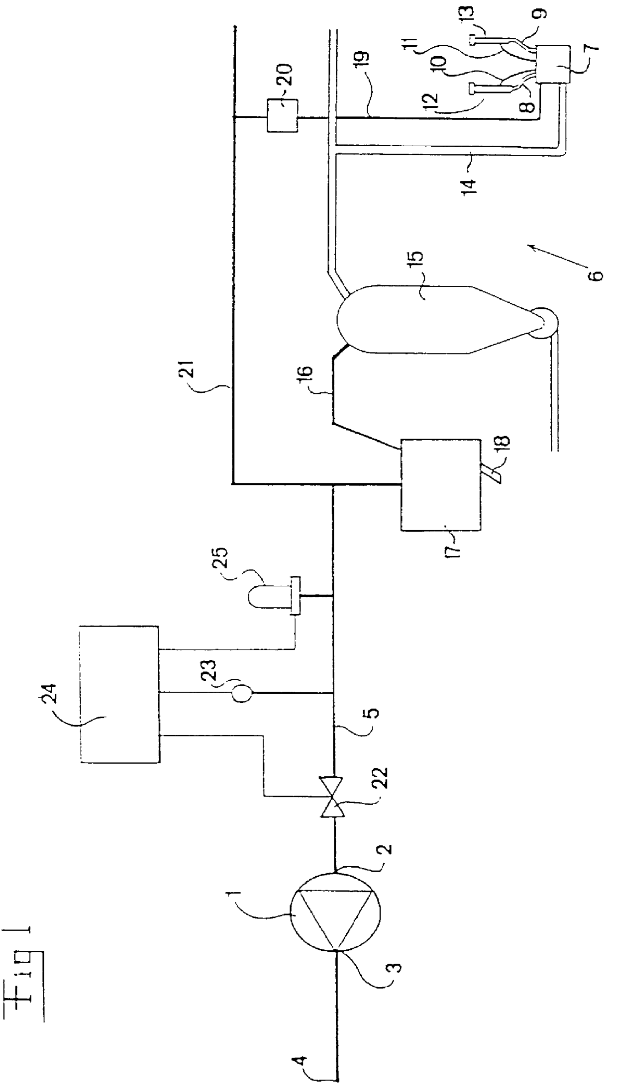
In FIG. 1 a milking apparatus, comprising a vacuum pump 1 having a suction side 2 and a pressure side 3, is partly disclosed. The pressure side 3 is possibly, via an oil separator and a silencer (not shown), connected to an outlet 4 connected to the atmosphere. The vacuum pump 1 is of a dynamic type, and preferably a so called radial compressor, which by means of blades, guides the incoming air at the suction side 2 radially outwards, thereby accelerating the air in radial direction by means of the centrifugal force. Thereafter, the remaining kinetic energy of the air is transformed by means of a diffuser to a pressure, such that the pressure ratio between the pressure side 3 and the suction side 2 of the vacuum pump 1 lies between about 1.7 and 2.7, preferably about 2.0. In order to produce this pressure ratio, the vacuum pump 1 may comprise one or more compressor stages. Other types of dynamic vacuum pumps may also be utilized, for example an axial compressor.

A suction side 2 of t...


PUM


Abstract

PCT No. PCT / SE96 / 00840 Sec. 371 Date Jan. 15, 1999 Sec. 102(e) Date Jan. 15, 1999 PCT Filed Jun. 26, 1996 PCT Pub. No. WO97 / 01270 PCT Pub. Date Jan. 16, 1997A milking apparatus includes a vacuum pump (1), a milking device (6) having at least one milking claw and teatcups (7, 12, 13) provided to be attached to an animal to be milked, and a conduit (5) connecting the milking claw and teatcups (7, 12, 13) to a suction side (2) of the vacuum pump and being adapted to transport a flow from the milking device (6). The vacuum pump (1) is of a dynamic type. Furthermore, a regulating device (22, 23, 24, 25) is adapted to maintain the vacuum level of the milking apparatus at a desired, constant value. Furthermore, the regulating device comprises a sensor (23) for sensing the actual vacuum level of the conduit (5) and a regulator adapted to control the vacuum level to the desired value by regulating the size of the flow through the conduit (5) and the vacuum pump (1) in response to the vacuum level sensed.

Description

1. Field of the InventionThe present invention relates to a method of regulating the vacuum level in a milking apparatus comprising a vacuum pump, a milking device having at least one milking means to be attached to an animal to be milked, and a conduit for the transport of a flow of air and connecting the milking device to a suction side of the vacuum pump. Moreover, the invention relates to a milking apparatus, comprising a vacuum pump, a milking device having at least one milking means provided to be attached to an animal to be milked, and a conduit connecting the milking device to a suction side of the vacuum pump and being adapted to transport a flow of air from the milking device.2. Description of the Prior ArtRegarding vacuum pumps, there are two predominant main types. The first type comprises deplacement pumps functioning by successively forming delimited gas volumes and transporting these under pressure increase through the pump. The second main type comprises dynamic pump...

Claims


Application Information

Patent Timeline
Patent Type & Authority Patents(United States)
IPC IPC(8): F04D27/02A01J5/04A01J5/00A01J5/007F04D27/00
CPCA01J5/007F04D19/04F04D27/0253A01J5/04
Inventor OLOFSSON, HANS
Owner DELAVAL HLDG AB
Why Eureka
Try Eureka