Method and apparatus for temporarily activating a brake in a weaving loom

a technology of weaving loom and brake, which is applied in the direction of weaving, textiles, papermaking, etc., can solve the problems of prolonging weaving operations, affecting the effect of weaving, so as to avoid delays in braking action

Inactive Publication Date: 2000-12-26
LINDAUER DORNIER GMBH
View PDF7 Cites 8 Cited by
  • Summary
  • Abstract
  • Description
  • Claims
  • Application Information

AI Technical Summary

Benefits of technology

to avoid so-called start markings or starting faults in a fabric by avoiding delays in the braking action applied to the loom main drive;
to time the loom stopping at sufficiently short time intervals to assure that the deposit of a braking action diminishing film on the brake components of the loom brake are avoided;

Problems solved by technology

However, prolonged weaving operations have their disadvantages as will be explained below.
While a continuous weaving operation without interruption is efficient in certain respects, it has its disadvantages because when the time comes that the loom must be stopped, fabric faults cannot be avoided, particularly in looms equipped with a clutch brake combination between the loom drive motor and the main loom drive shaft.
This drawback is due to the fact that the clutch brake combination is subject to a certain time delay between the stop signal and the actual stopping of the loom drive shaft and such delay becomes longer in duration the longer the loom was operating without interruption.
Observations in practice have shown that a weaving operation continuing for several hours on high speed looms without interruption of the weaving operation have the disadvantage that the environmental conditions caused by such continuous weaving adversely influence the braking characteristic of the loom brake, specifically the braking operation of the clutch brake combination.
This adverse influence causes the above delay between the stop signal and the actual stopping of the loom drive shaft due to the high relative humidity in the weaving hall and the high fly lint which in combination form a sliding film on the brake components of the clutch brake combination.
This delay in the braking action following the stop signal causes misaligned positions of the main loom drive shaft compared to positions that the main loom drive shaft should assume in accordance with programmed brake and stop positions.
Thus, the delay in the braking action leads, for example to the fact that the sley and thus the reed mounted on the sley perform a beat-up along the beat-up line which in turn leads to densification of the fabric.
As a result, when the loom is started again, so-called start markings become visible in the fabric which diminishes the fabric quality.

Method used


Image

  • Method and apparatus for temporarily activating a brake in a weaving loom

Examples


Embodiment Construction

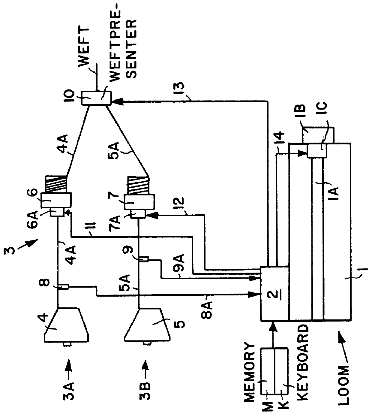
A loom 1 comprises a main loom drive shaft 1A driven by a main loom drive motor 1B through a clutch brake combination 1C. The loom also comprises a central loom control 2 including a memory M and an input such as a keyboard K. The memory M stores loom control programs and the input K permits the entry of further programs or program changes.

The loom 1 is equipped with a weft supply system 3 comprising at least two weft supply paths 3A, 3B. The path 3A comprises a weft supply spool 4 feeding a weft thread 4A to a feeder 6 which in turn supplies the weft thread 4A to a weft presenter or weft inserter 10 which may, for example, be a weft insertion nozzle or the like.

The weft supply path 3B also comprises a supply spool 5 feeding a weft thread 5A to a feeder 7 which in turn feeds the thread 5A to the weft presenter or inserter 10.

A first weft monitor 8 monitors the supply of the weft thread 4A and is positioned between the spool 4 and the feeder 6. The sensor is a so-called weft stop mot...


PUM


Abstract

The brake components of a clutch brake combination in an automatic high speed loom are periodically cleaned to avoid delays in the brake action that occur following a prolonged loom operation without a stopping. The stopping signal is either derived from randomly occurring events or criteria such as a weft breakage or similar criteria on the one hand, or when a criterium stored in the memory or program of the loom control occurs. The respective control signal is generated in response to whichever criterium occurs first.

Description

PRIORITY CLAIMThis application is based on and claims the priority under 35 U.S.C. .sctn.119 of German Patent Application 199 15 349.3, filed on Apr. 6, 1999, the entire disclosure of which is incorporated herein by reference.The invention relates to a method and apparatus for temporarily activating a brake in a weaving loom to keep the brake clean thereby assuring a rapid braking action when a loom is to be stopped by avoiding brake conditions that can cause delays in the effectiveness of the brake response characteristic.BACKGROUND INFORMATIONConventionally, efforts have been made to continue the weaving operation of a loom as long as possible by avoiding interruption of the weaving process. However, prolonged weaving operations have their disadvantages as will be explained below. In order to enable an uninterrupted weaving operation for hours on end, certain conditions must be met. A first condition is that the supply of weft yarns and warp yarns is substantially continuous. Anot...

Claims


Application Information

Patent Timeline
Patent Type & Authority Patents(United States)
IPC IPC(8): D03D47/34D03D51/00D03D51/34D03D51/10
CPCD03D51/00D03D47/34D03D51/08D03D51/002D03D51/34
Inventor KRUMM, VALENTIN
Owner LINDAUER DORNIER GMBH
Why Eureka
Try Eureka