Microstrip antenna

Inactive Publication Date: 2000-12-26
RADIO FREQUENCY SYST
View PDF10 Cites 17 Cited by
  • Summary
  • Abstract
  • Description
  • Claims
  • Application Information

AI Technical Summary

Problems solved by technology

Because significant time is needed for machining, assembly and tuning of each antenna, the cost of manufacturing such antennas is relatively high.
Also, b

Method used


Image

  • Microstrip antenna
  • Microstrip antenna
  • Microstrip antenna

Examples


Embodiment Construction

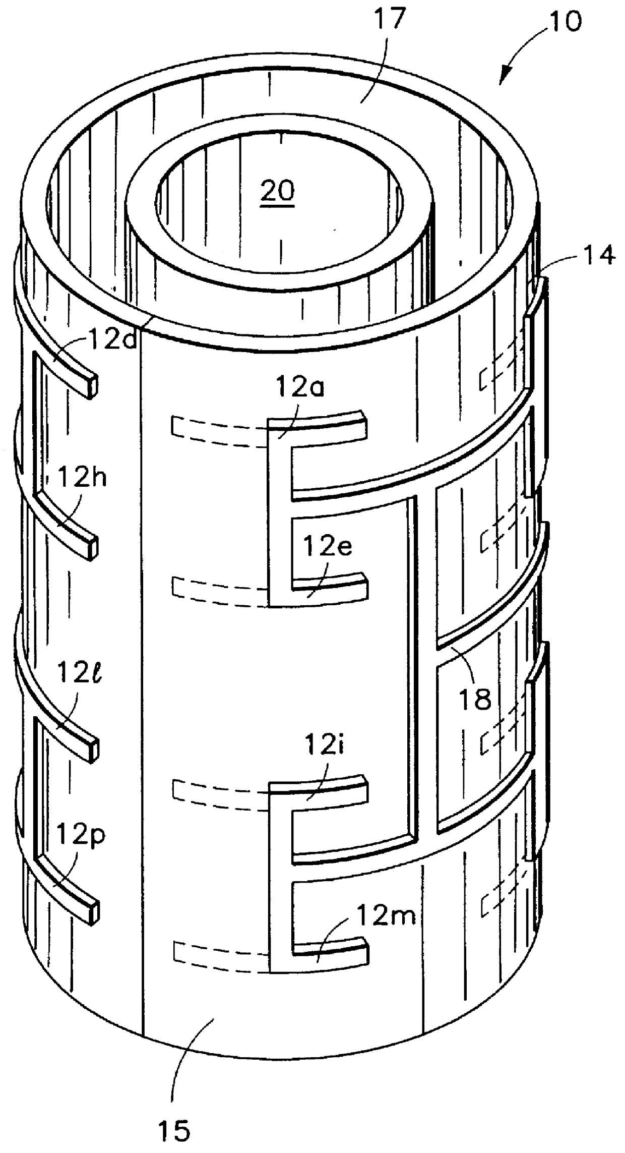
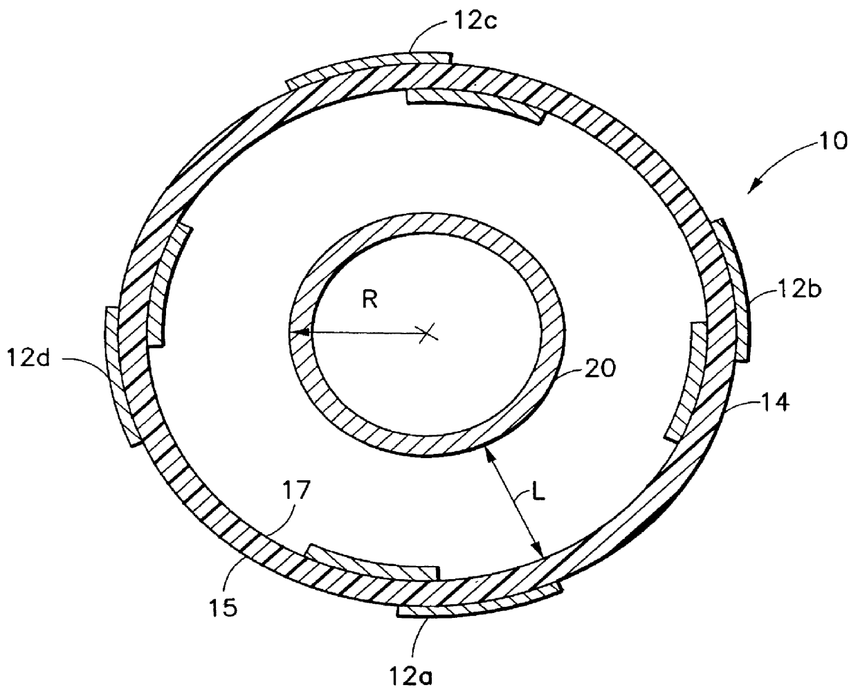
Referring generally to the drawings, there is shown a microstrip antenna 10 made according to the present invention. The antenna 10 is formed by providing one and preferably a plurality of dipole microstrip radiating elements 12a-12p on a substantially cylindrical dielectric tube 14. The dielectric tube 14 may made with any dielectric material, and preferably, the tube 14 is formed out of polytetrafluoroethylene. The tube 14 has an exterior substantially cylindrical surface 15 and an interior substantially cylindrical surface 17. The thickness of the tube 14 is in the range of about 0.003 to 0.05 .lambda..sub.0. At S-band radio frequencies (2.1 to 2.7 Ghz), .lambda..sub.0 is typically in the range of about 11 to 14 cm.

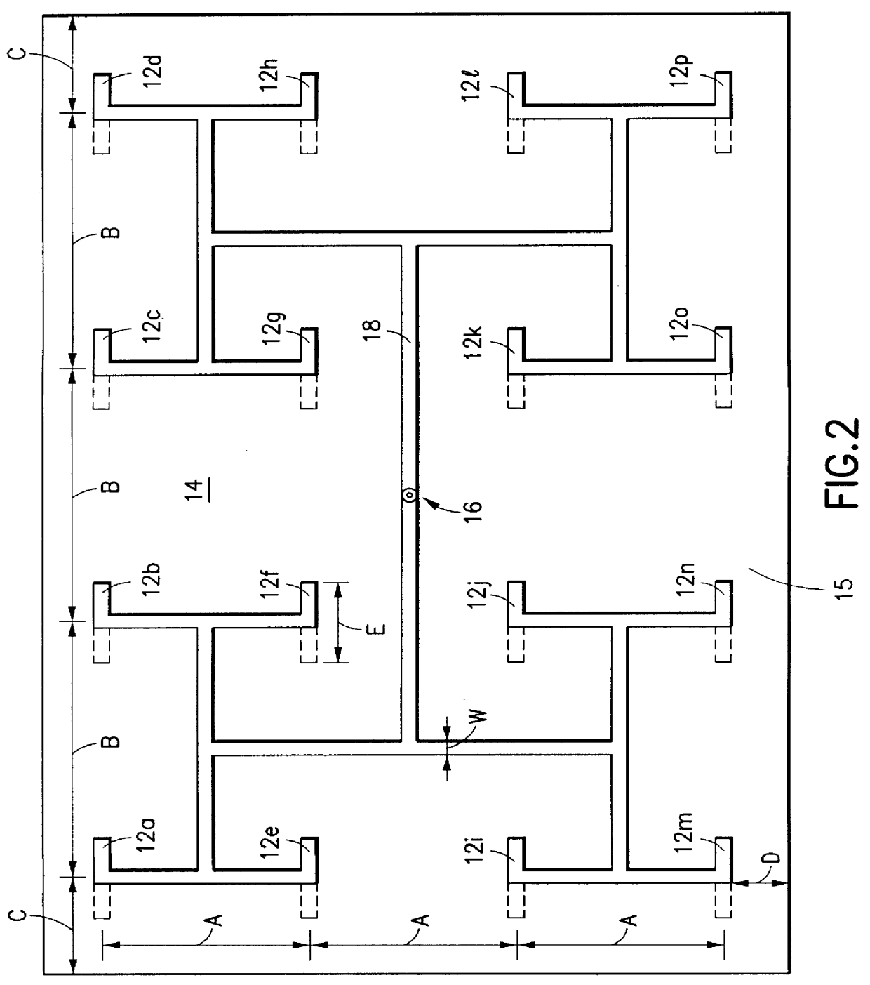
As illustrated in the isometric view of FIG. 1 and the plan view of FIG. 2, the microstrip dipole radiating elements 12a-12p of the plurality are distributed about the tube 14 in an array of N circumferentially distributed columns and M axially distributed rows. In the...


PUM


Abstract

A microstrip antenna suitable for omnidirectional S-band operation is formed by the application of a plurality of microstrip radiating elements to the exterior surface of a dielectric tube. The microstrip radiating elements are fed by a branched microstrip input feed line connected to the elements. In the illustrated embodiment, the microstrip radiating elements are fed in-phase by feed line. A substantially cylindrical reflector tube is disposed within the dielectric tube.

Description

1. Field of the InventionThe present invention generally relates to antennas. More particularly, the present invention relates to a microstrip antenna having a generally cylindrical shape.2. Description of the Related ArtCurrent state of the art omnidirectional S-band radio frequency antennas (2.1-2.7 GHz) are made from a large number of machined parts. Such parts must be assembled and tuned. Because significant time is needed for machining, assembly and tuning of each antenna, the cost of manufacturing such antennas is relatively high. Also, because such antennas are fabricated from a large number of assembled parts, these antennas may be easily damaged by the wind and other elements of nature. Periodically, the machined components forming such antennas may need to be adjusted or reassembled so as to ensure that these antennas are properly tuned.It is a primary object of the present invention to provide a radio frequency microstrip antenna that is inexpensive to manufacture, is rel...

Claims


Application Information

Patent Timeline
IPC IPC(8): H01Q9/28H01Q9/04H01Q21/20H01Q19/10H01Q1/24H01Q21/06
CPCH01Q1/246H01Q9/285H01Q21/205H01Q21/062H01Q19/108
Inventor AUDENAERDE, KARL R.SABO, STEVELEE, JOON Y.
Owner RADIO FREQUENCY SYST
Why Eureka
Try Eureka