Multiplication method and multiplication circuit

a multiplication method and circuit technology, applied in the field of multiplication methods and multiplication circuits, can solve problems such as increasing the amount of processing

Inactive Publication Date: 2000-12-26
PANASONIC CORP
View PDF22 Cites 14 Cited by
  • Summary
  • Abstract
  • Description
  • Claims
  • Application Information

AI Technical Summary

Problems solved by technology

This causes a problem of incre

Method used


Image

  • Multiplication method and multiplication circuit
  • Multiplication method and multiplication circuit
  • Multiplication method and multiplication circuit

Examples


first embodiment

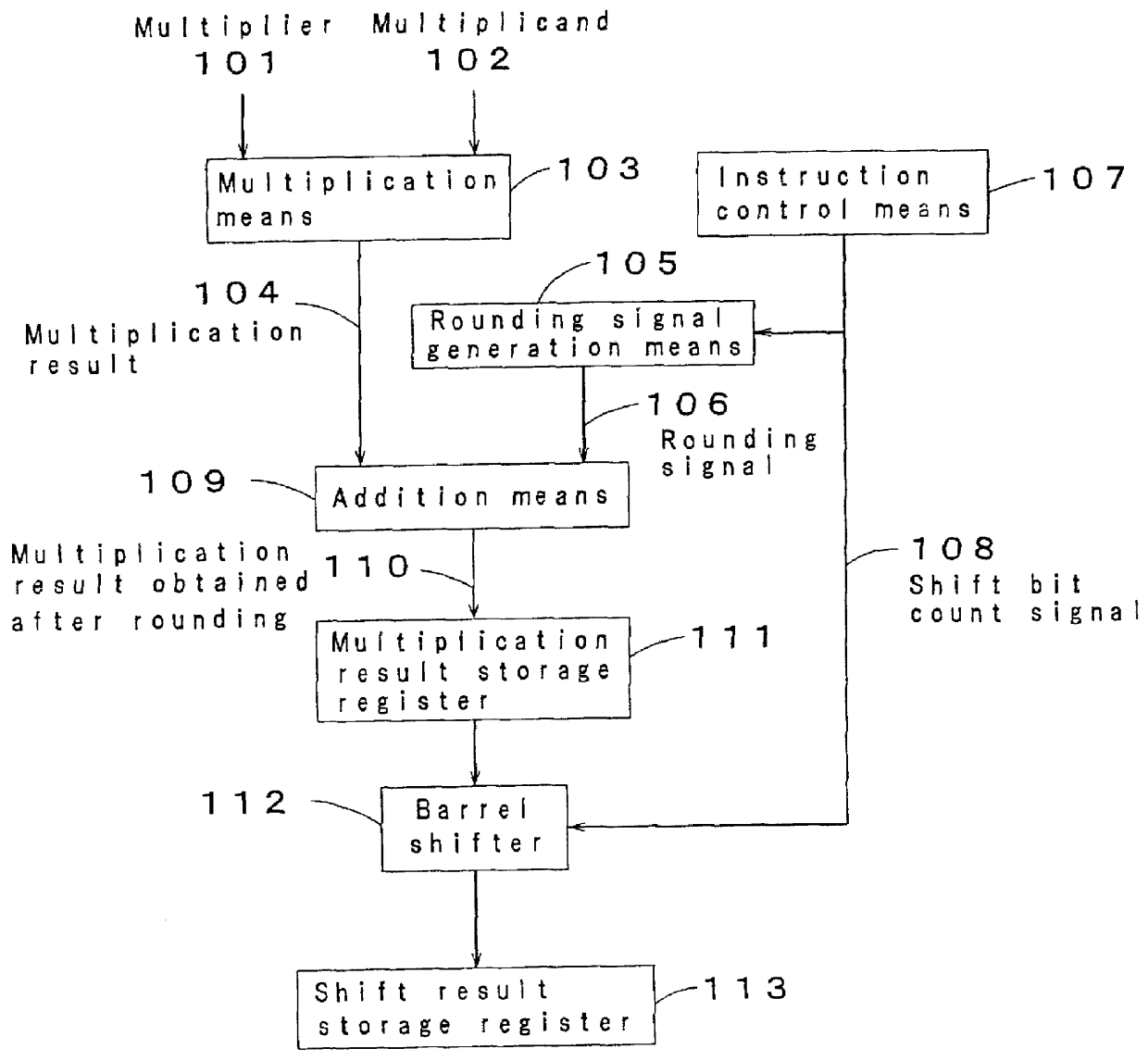
FIG. 1 is a block diagram showing a multiplication circuit in accordance with a first embodiment of the present invention. Referring to FIG. 1, numeral 101 designates a multiplier, numeral 102 designates a multiplicand, numeral 103 designates a multiplication means, numeral 104 designates a multiplication result used as the output of the multiplication means 103, numeral 105 designates a rounding signal generation means, numeral 106 designates a rounding signal used as the output of the rounding signal generation means 105, numeral 107 designates an instruction control means of a processor, numeral 108 designates a shift bit count signal controlled by the instruction control means 107, numeral 109 designates an addition means, numeral 110 designates a multiplication result obtained after rounding as the output of the addition means 109, numeral 111 designates a register used as a means for storing the multiplication result 110 obtained after rounding, numeral 112 designates a barrel...

second embodiment

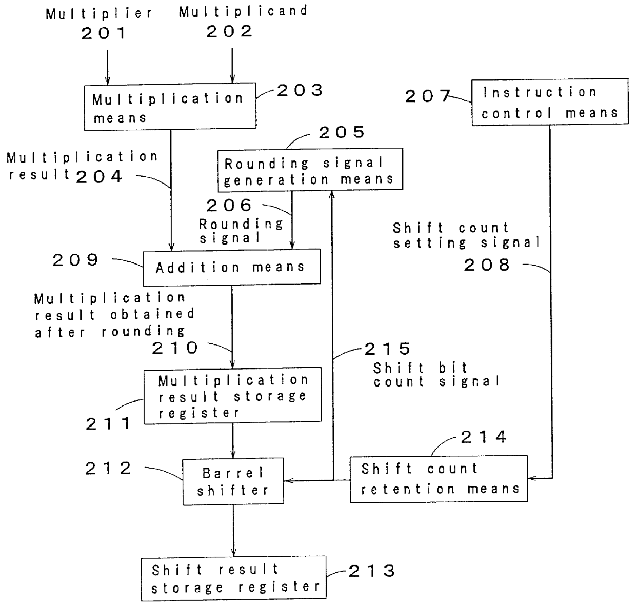
The second embodiment differs from the first embodiment in that the second embodiment is provided with the shift count retention means 214. Other than the shift count retention means 214, the configuration and operation are the same as those of the first embodiment, and their descriptions are omitted. The shift count setting signal 208 is temporarily stored in the shift count retention means 214. The output of the shift count retention means 214 is input to the rounding signal generation means 205 and the barrel shifter 212 as the shift bit count signal 215. In other words, in the second embodiment, a shift count can be set in the shift count retention means 214 before the issue of the multiplication instruction by adding the shift count retention means 214 to the configuration of the first embodiment.

As described above, in addition to the effects of the first embodiment, by providing the shift count retention means 214 in the present embodiment, the shift count can be set beforehan...

third embodiment

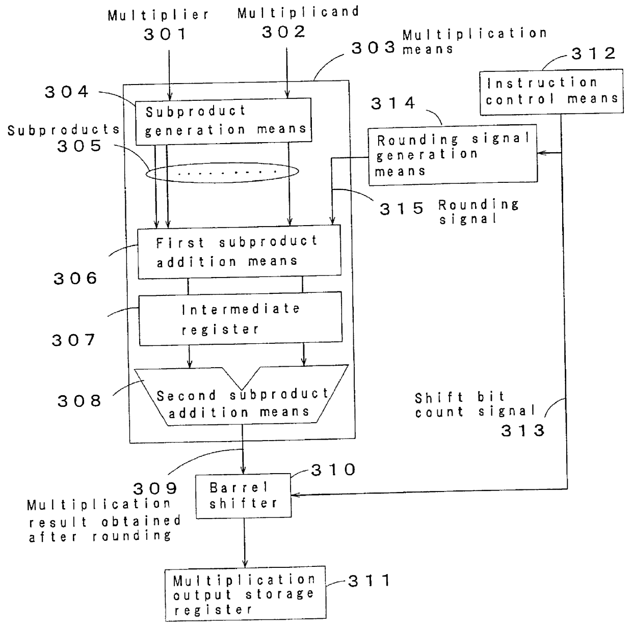
FIG. 3 is a block diagram showing a multiplication circuit in accordance with a third embodiment of the present invention. Referring to FIG. 3, numeral 301 designates a multiplier, numeral 302 designates a multiplicand, numeral 303 designates a multiplication means, numeral 304 designates a subproduct generation means as a component of the multiplication means 303, numeral 305 designates subproducts as the output of the subproduct generation means 304, numeral 306 designates a first subproduct addition means as a component of the multiplication means 303, numeral 307 designates an intermediate register for temporarily storing an intermediate result obtained in the first subproduct addition means 306, numeral 308 designates a second subproduct addition means for adding the output of the intermediate register 307 and used as a component of the multiplication means 303, numeral 309 designates a multiplication result obtained after rounding and used as the output of the second subproduc...


PUM


Abstract

A multiplication method and a multiplication circuit, wherein a multiplicand is multiplied by a multiplier using a multiplication process, the result of the multiplication is added by an addition process to a rounding signal to be output from a rounding signal generation process, and the result of the addition, i.e., a multiplication result obtained after rounding, is stored in a register. By a barrel shifter, the multiplication result obtained after rounding stored in the register is shifted by a bit count indicated by a shift bit count signal. The shift bit count signal output from an instruction control process is input to the barrel shifter and a rounding signal generation process. The rounding signal generation process generates a rounding signal on the basis of the shift bit count signal indicating the bit count used to shift the multiplication result after rounding. By carrying out a rounding process in the addition process by using the rounding signal, the rounding process can be carried out at an appropriate position desired by the user without increasing instruction code or storage.

Description

1. Field of the InventionThe present invention relates to a multiplication method and a multiplication circuit for executing fixed point multiplication instructions used for digital signal processing in image and sound processing fields.2. Prior ArtFIG. 9 is a conceptual view showing a multiplication method in a multiplication instruction provided with a conventional rounding function.This conventional multiplication method is carried out as described below. After a multiplication result 903 obtained by the multiplication of a multiplier 901 and a multiplicand 902 is rounded by adding 1 as a rounding signal 906 at a predetermined rounding position 905 where rounding is executed, a bit range 908 up to the rounding position 905 is discarded. The result thus obtained is taken as a multiplication result 907 subjected to rounding.In the conventional example shown in FIG. 9, however, when multiplication requiring rounding is executed, 1 is added at the predetermined position 905 without e...

Claims


Application Information

Patent Timeline
IPC IPC(8): G06F5/01G06F7/48G06F7/52
CPCG06F5/01G06F7/523G06F7/49963G06F7/52
Inventor SAISHI, MANAKUROHMARU, SHUNICHI
Owner PANASONIC CORP
Why Eureka
Try Eureka