Single screw bridgeplate

a single screw and bridge plate technology, applied in railway components, locomotives, transportation and packaging, etc., can solve the problems of difficult installation of devices for facilitating access to rail vehicles with extendable ramp assemblies, affecting the and requiring extensive modification of vehicle structures. to achieve the effect of convenient mounting and convenient egress and ingress of passengers

Inactive Publication Date: 2001-01-02
WESTINGHOUSE AIR BRAKE CO
View PDF2 Cites 35 Cited by
  • Summary
  • Abstract
  • Description
  • Claims
  • Application Information

AI Technical Summary

Benefits of technology

Another object of the present invention is to provide a bridge plate which serves as a ramp for accommodating a slight difference in elevation between the floor of a transit vehicle and an adjacent platform to facilitate egress and ingress of passengers.
Still another object of the present invention is to provide a bridge plate assembly which can easily be mounted on a transit vehicle without extensive modification of the transit vehicle.

Problems solved by technology

However, these devices either do not provide smooth transition between the car floor and platform or require extensive modification to the vehicle structure in order to accommodate the operative portions of the bridge plate.
U.S. Pat. No. 5,537,869, entitled DEVICE FOR FACILITATING ACCESS TO A RAIL VEHICLE HAVING EXTENDABLE RAMP ASSEMBLY is difficult to install because principal portions of it are mounted within the floor of the transit vehicle, and require cutting away portions of the floor support structure.

Method used


Image

  • Single screw bridgeplate
  • Single screw bridgeplate
  • Single screw bridgeplate

Examples


Embodiment Construction

, particularly, when the detailed description is taken in conjunction with the attached drawing Figures and with the appended claims.

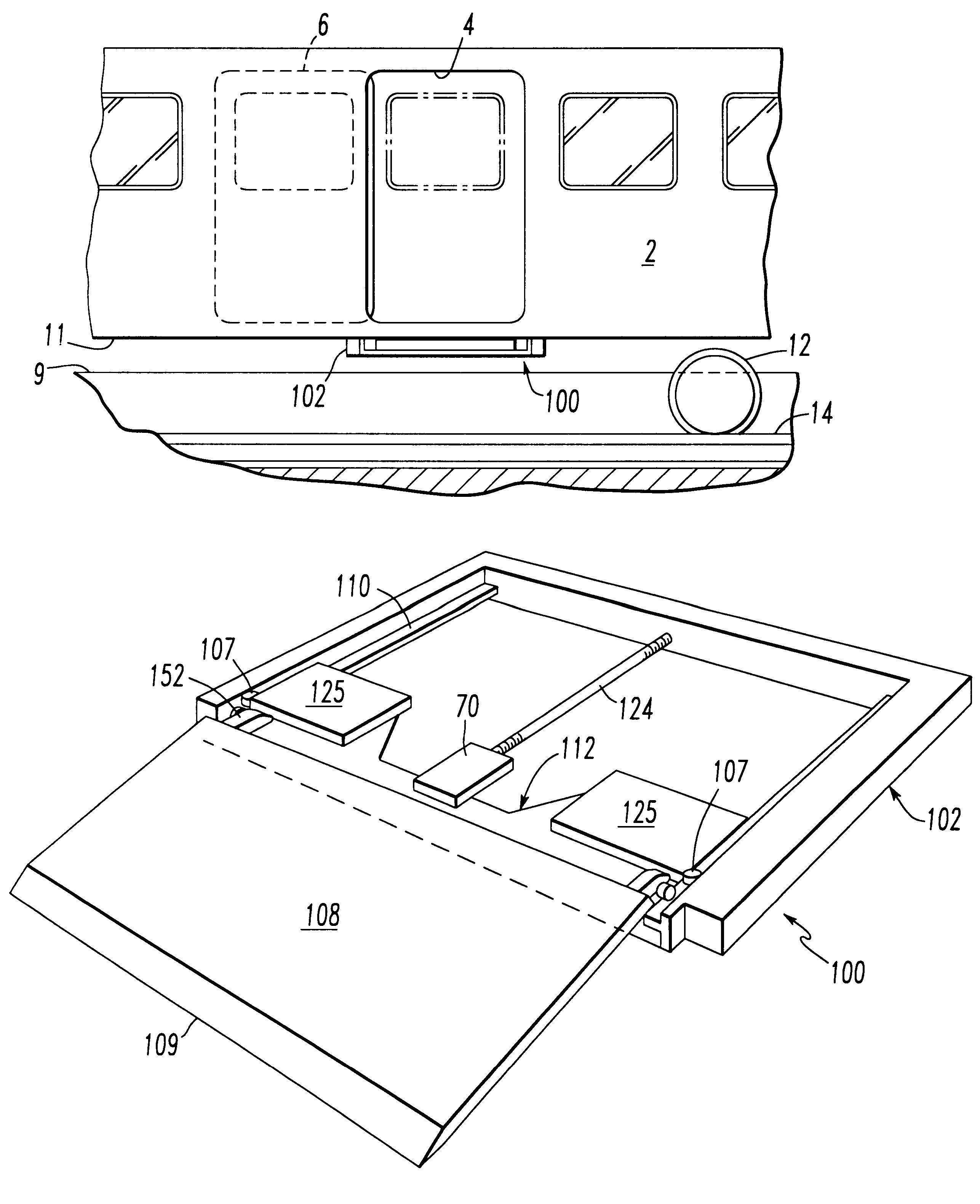
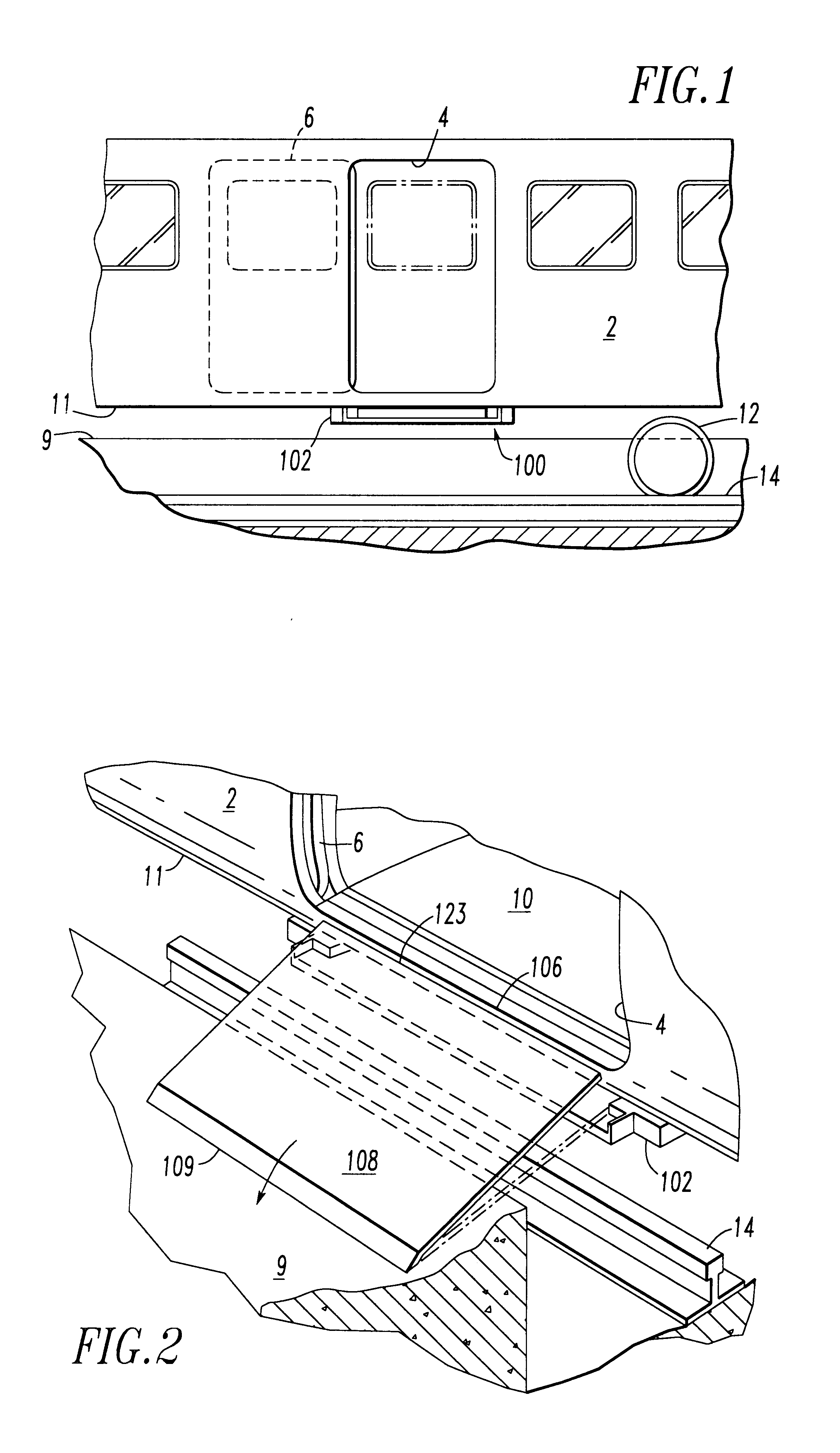
FIG. 1 shows a transit vehicle having the cartridge bridge plate assembly of the present invention attached to a floor structure of a railway transit vehicle.

FIG. 2 shows the bridge plate in an extended position to provide continuous surface between the floor of the transit vehicle and an adjacent platform.

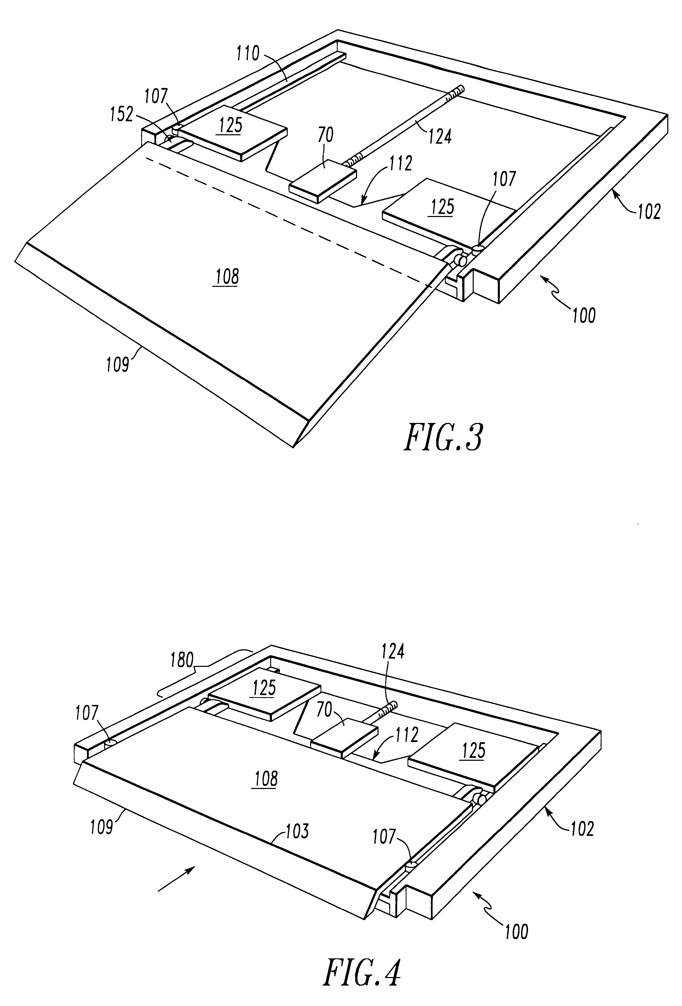
FFIG. 3 is a schematic illustration showing principal features of the assembly with the bridge plate in the extended position.

FIG. 4 is a schematic illustration showing principal features of the assembly with the bridge plate in a stowed position.

FIG. 5 is a portion of an assembly drawing of a presently preferred embodiment which shows a portion of the frame, the motor, a portion of the drive screw and a portion of the positioning means for the bridge plate.

FIG. 6 shows a portion of the presently preferred embodiment showing portion of the frame, a p...


PUM


Abstract

The present invention is a cartridge bridge plate assembly for mounting under a floor structure of a transit vehicle adjacent a door opening. It has a frame assembly and means for attaching the frame assembly underneath the floor structure of the vehicle. It has a bridge plate for covering a gap between the floor of the vehicle and an adjacent surface to facilitate passenger ingress and egress when the vehicle is stopped. It has a bridge plate positioning means for positioning the bridge plate and accommodating motion of the bridge plate from a stowed position within the frame assembly to an extended position for covering the gap. A motor is connected to the bridge plate positioning means for moving the bridge plate from the stowed position to the extended position and from the extended position to the stowed position. The system includes a power connection to the motor, and a drive screw connected to and rotated by the motor. It has a drive nut engaging the drive screw to be translated thereby, the drive nut having mechanical connection to the bridge plate positioning means to move the bridge plate from the stowed position to the extended position and from the extended position to the stowed position. The system also has an elevating means connected to the bridge plate positioning means for elevating an inner edge of the bridge plate to match an elevation of the floor surface of the transit vehicle.

Description

The present invention relates, in general, to door systems for mass transit vehicles, and, more particularly, relates to bridge plates for facilitating ingress into and egress from mass transit vehicles.This invention relates generally to providing improved passenger access to mass transit vehicles, and more particularly concerns devices which extend outward from the side wall of a mass transit vehicle generally at floor level in order to bridge or cover any existing gap and level difference between the transit vehicle floor and an adjacent platform or other exit area.Known devices which attempt to accomplish the above described "bridging" action include European Patent Application 94400475.3 (Publication No. 0618125A1), and European Paten Application 86113060.7 (Publication No. 08.04.87). However, these devices either do not provide smooth transition between the car floor and platform or require extensive modification to the vehicle structure in order to accommodate the operative p...

Claims


Application Information

Patent Timeline
Patent Type & Authority Patents(United States)
IPC IPC(8): B61D23/00B61D23/02
CPCB61D23/025
Inventor LAVERY, EVINGOLEMIS, FOTIOS
Owner WESTINGHOUSE AIR BRAKE CO
Why Eureka
Try Eureka