Release mechanism for a motor vehicle friction clutch

a technology for releasing mechanisms and clutches, which is applied in automatic clutches, mechanical devices, transportation and packaging, etc., can solve problems such as the clutch is not yet fully released and the different components of the clutch wear out during operation

Inactive Publication Date: 2001-01-02
MANNESMANN SACHS AG
View PDF7 Cites 13 Cited by
  • Summary
  • Abstract
  • Description
  • Claims
  • Application Information

AI Technical Summary

Benefits of technology

When the pressure fluid is compressed air, the existing pneumatic system in utility vehicles can be utilized in a simple manner to provide the shifting force for carrying out the shifting processes. Further, the use of compressed air for generating the shifting force has the advantage that wear due to advanced operating age and which typically leads to leakage of fluid will not result in detrimental impairment of the function of the entire system since leakage of compressed air can be tolerated to a certain extent.

Problems solved by technology

However, a problem associated with this mechanism is that there is no exact relationship between clutch pedal actuation and the actual release state in the case of air pressure actuation of the clutch, so that even when the clutch switch initiates shifting, it is possible that the clutch is not yet in its fully released state.
As is well known, different components of motor vehicle clutches wear out during operation, especially the clutch friction linings at the clutch disk or disks.

Method used


Image

  • Release mechanism for a motor vehicle friction clutch
  • Release mechanism for a motor vehicle friction clutch
  • Release mechanism for a motor vehicle friction clutch

Examples


Embodiment Construction

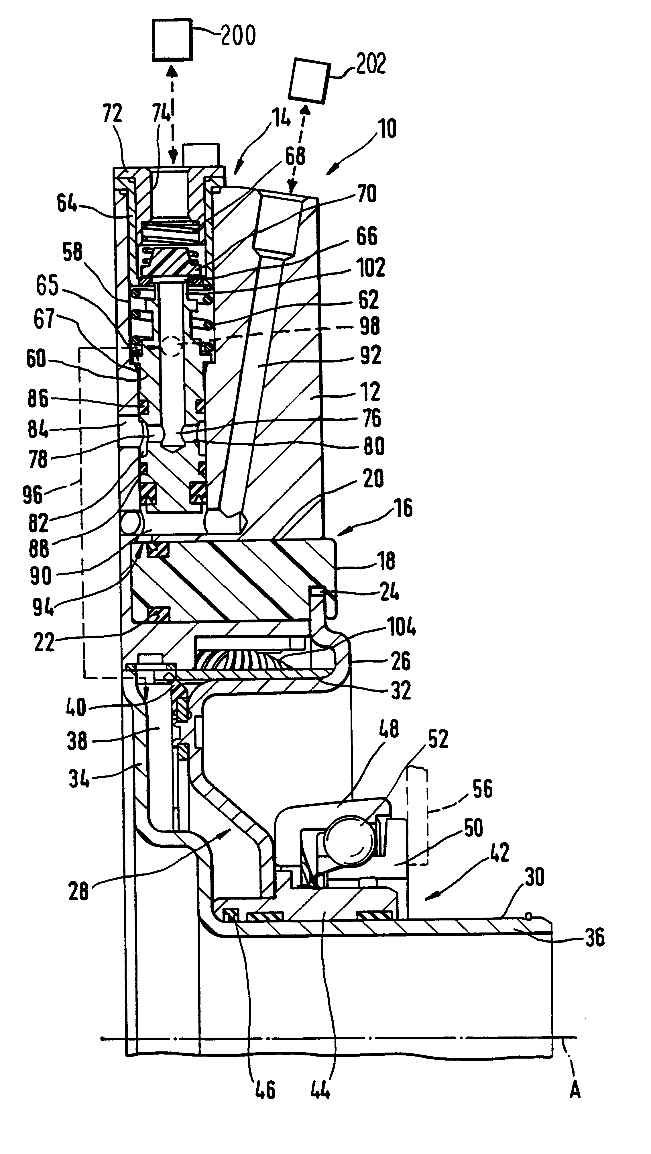
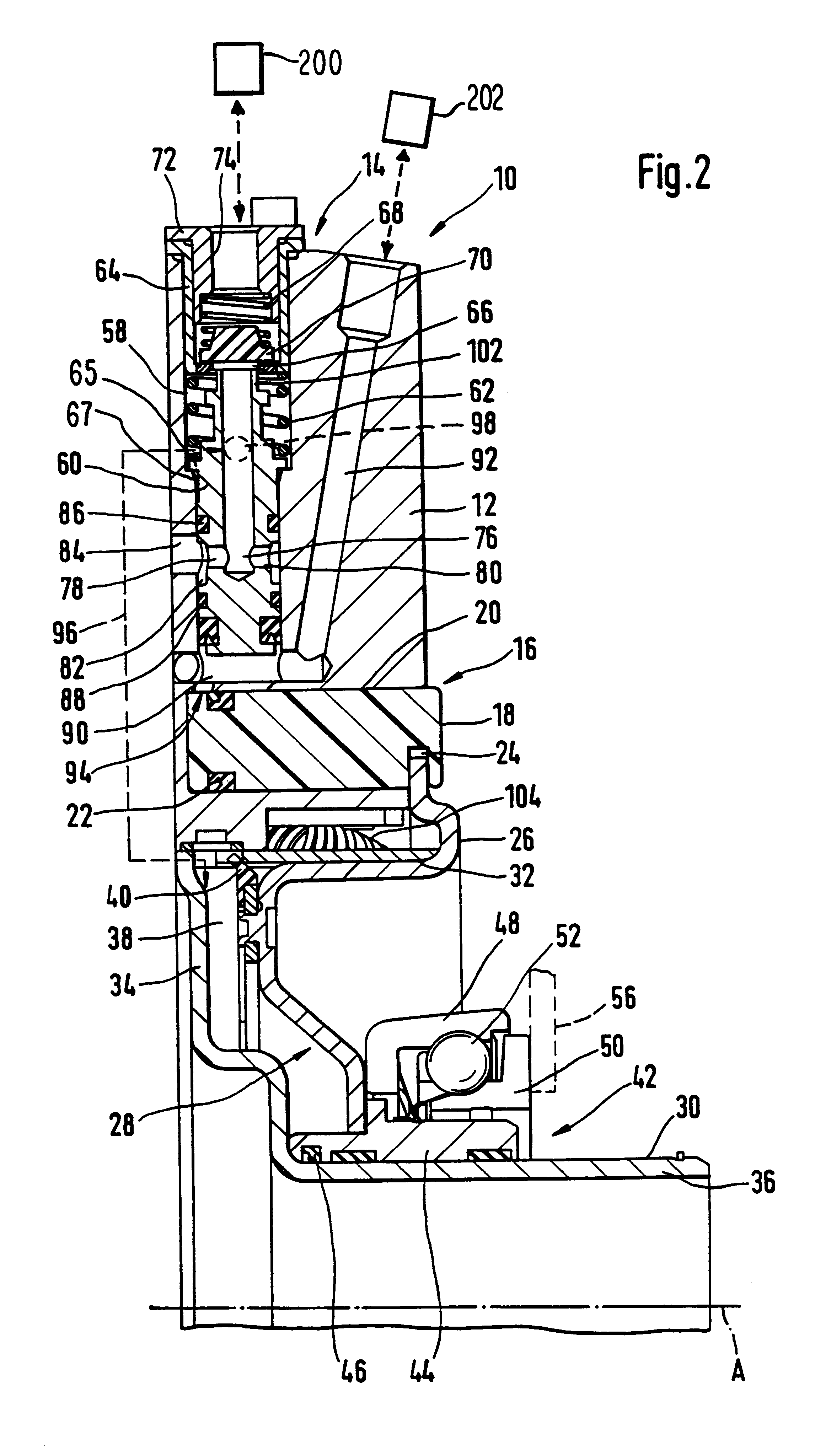
Initially, the construction and manner of functioning of an embodiment of release mechanism 10 in accordance with the present invention, as is preferably used in commercial or utility vehicles, will be described with reference to FIG. 2. As shown, the release mechanism 10 is constructed in such a way that it encloses an axis of rotation A of a motor vehicle clutch (not shown) so as to be substantially concentric thereto and different components of the clutch are also constructed concentrically with respect to the axis of rotation A.

Visible from the outside is a housing 12 of the release mechanism 10 in which a valve arrangement 14, described in the following, is incorporated. A measurement arrangement 16 which has a measurement piston 18 which is displaceable in the direction of the axis of rotation A is located radially inside of the valve arrangement 14. The measurement piston 18 is arranged in a measurement cylinder 20 that is formed in the housing 12 and opens toward one axial s...


PUM


Abstract

A release mechanism for a motor vehicle friction clutch for cooperation with a motor vehicle transmission having subdivided switching steps. The mechanism includes a release member displaceable by a compressed air for carrying out a clutch release process, a valve arrangement for selectively supplying the compressed air, and a measurement arrangement for detecting an actual release position of the release member. The valve arrangement carries out the application of pressure fluid to the release member in accordance with (1) a reference variable provided by an actuation arrangement and which represents a reference release position of the release member, and (2) the detected actual release position. The measurement arrangement is so constructed that when the detected actual release position exceeds a predetermined switching threshold release position, a shifting signal is provided for shifting the transmission in subdivided switching steps.

Description

1. Field of the InventionThe present invention relates to clutch release mechanisms for a motor vehicle friction clutch for use with a motor vehicle transmission, especially commercial or utility vehicle transmissions, with subdivided shifting or switching steps. More particularly, the present invention relates to a release mechanism actuatable by compressed air.2. Description of the Related ArtA release mechanism is known from German patent publication DE 197 16 600 A1. This known release mechanism in which the releasing force is generated by air pressure and the extent of the release actuation is predetermined by a hydraulic system coupled with a clutch pedal is basically constructed for use with vehicle transmissions, especially in commercial or utility vehicle transmissions, which are constructed with or without subdivided switching steps. Transmissions in which the switching steps are subdivided comprise a subdivided stage which can be switched on or off as desired by the drive...

Claims


Application Information

Patent Timeline
Patent Type & Authority Patents(United States)
IPC IPC(8): F16D25/08F16D48/00F16D48/02
CPCF16D25/083F16D25/14F16D48/02F16D2048/0221F16D2500/10412F16D2500/1045F16D2500/1112F16D2500/3026F16D2500/70488
Inventor LINDNER, JOACHIM
Owner MANNESMANN SACHS AG
Why Eureka
Try Eureka