
Pipette with improved pipette tip and mounting shaft

Inactive Publication Date: 2001-01-02
RAININ INSTR
View PDF5 Cites 110 Cited by
  • Summary
  • Abstract
  • Description
  • Claims
  • Application Information

AI Technical Summary

Benefits of technology

To meet the heretofore unattainable ideal criteria that disposable plastic pipette tips (i) be easily mountable on a pipette tip mounting shaft to form a fluid tight connection with the shaft which is so secure that the tip will not rock laterally on or accidently dislodge from the shaft during normal pipette use and (ii) then be easily ejectable from the mounting shaft by application of minimal axial mounting and ejection forces, e.g. forces approaching one pound or less, the present invention has adopted a unique approach. It incorporates in an air displacement pipette the concept of axially spaced annular sealing and substantially cylindrical lateral support zones and regions on the pipette's mounting shaft and tip, respectively. Further, it provides means for insuring uniform depth of mounting shaft penetration into the pipette tip to maintain uniform tip interference with the mounting shaft as successive tips are mounted on and ejected from the mounting shaft.
Because of the above described cooperative structural features of the pipette tip and mounting shaft, the pipette tip combination of the present invention has proven to only require axial pipette tip mounting and ejection forces substantially equal to or less than one pound and to provide a stable air-tight seal of the tip on the shaft which is secure against undesired lateral rocking of the pipette tip on the mounting shaft. Thus, the combination comprising the present invention requires a pipette user to generate so little hand and thumb force that repeated mounting and ejection of such pipette tips is unlikely to result in repetitive stress injury.
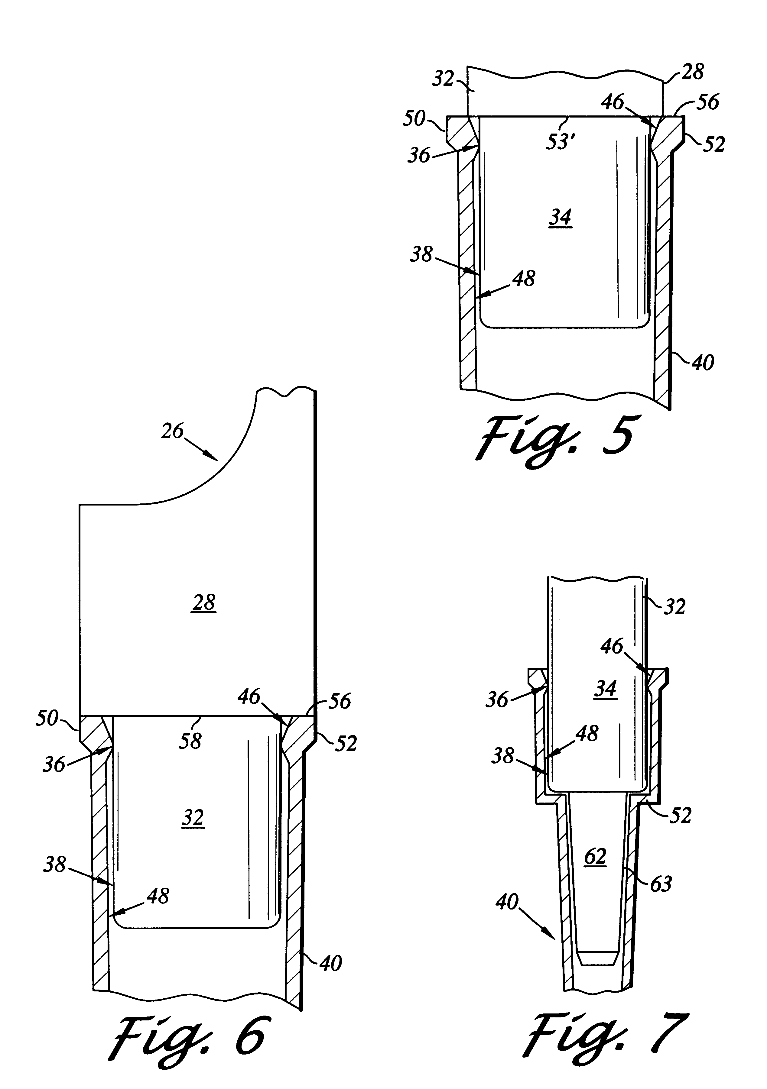
FIG. 7 is a cross sectional side view of an alternative embodiment of the pipette tip and mounting shaft combination of the present invention including a mounting shaft extension for reducing air volume effects associated with air displacement pipettes.
FIG. 10 is a graph comparing the lateral stability of a pipette tip of the pipette tip / mounting shaft combination of the present invention on the mounting shaft with the lateral stability of a standard pipette tip and "soft seal" tip on a standard mounting shaft for tips mounted with different pipette tip insertion forces.

Problems solved by technology

This allows for some minimal contact between the support zone and region without creating a secondary air tight seal which would result in an undesired increase in the axial forces required to mount and eject the pipette tip on and from the shaft.

Method used


Image

  • Pipette with improved pipette tip and mounting shaft
  • Pipette with improved pipette tip and mounting shaft
  • Pipette with improved pipette tip and mounting shaft

Examples


Embodiment Construction

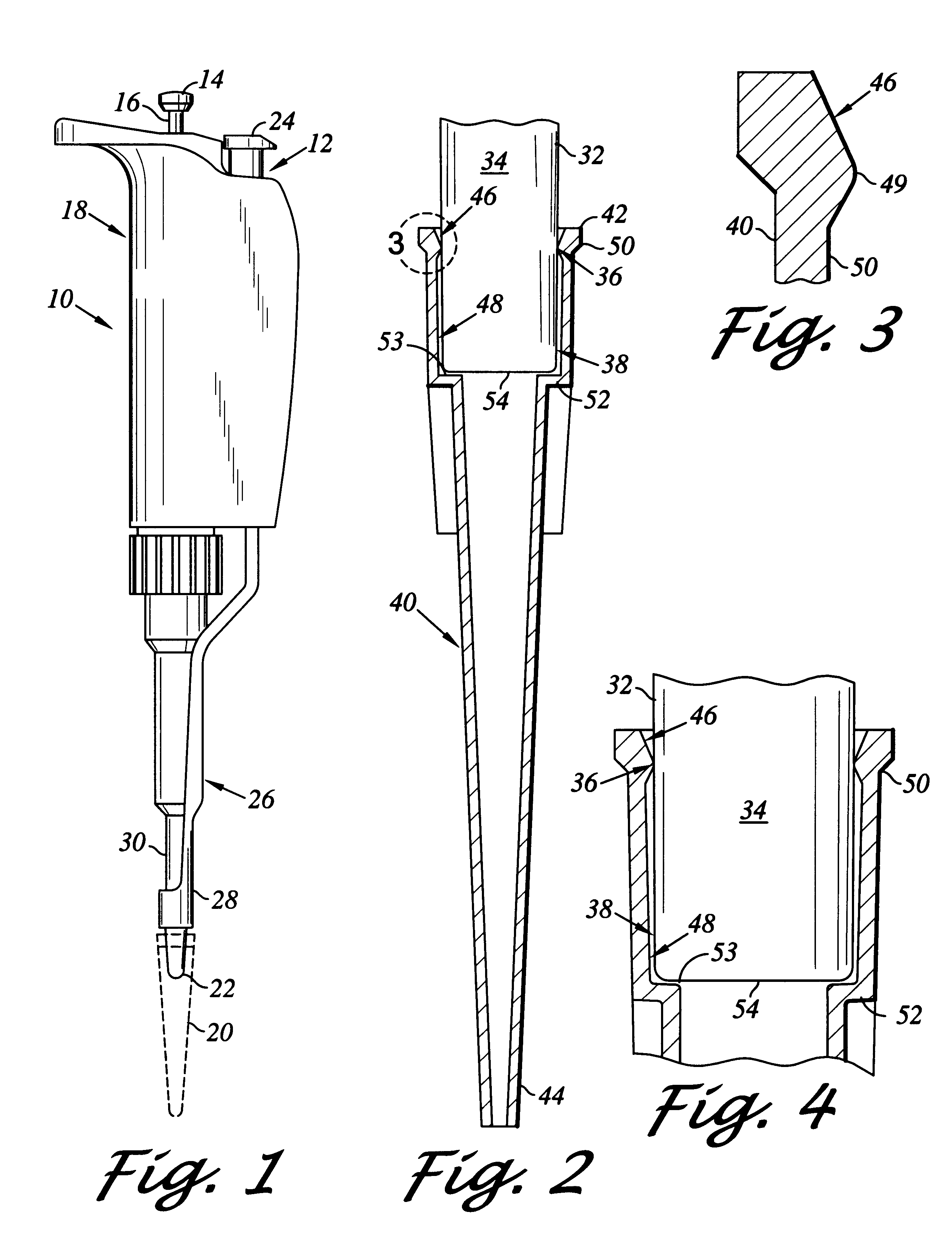
FIG. 1 illustrates a standard manual pipette resembling the PIPETMAN pipette sold exclusively in the United States by the Rainin Instrument Co. Inc., assignee of the present invention. The manual pipette is designated in FIG. 1 by the number 10 and includes a pipette tip ejector mechanism 12 described in U.S. Pat. No. 3,991,617 issued Nov. 16, 1976, which is incorporated herein by this reference.

The pipette 10 comprises a push button 14 connected by a rod 16 to a piston (not shown) located in the body or housing 18 of the pipette. The push button 14 may be depressed by a user exerting a downward force on the push button to cause downward movement of the piston of the pipette. When the push button 14 is released, a quantity of liquid to be sampled is sucked into a disposable pipette tip 20 releasably secured to a lower end of a pipette tip mounting shaft 22 of the pipette. The sample then may be transferred into another vessel by once more exerting a downward force on the push button...


PUM


Abstract

An air displacement pipette having axially spaced annular sealing and substantially cylindrical lateral support zones and regions on the pipette's mounting shaft and tip, respectively, in combination with structure for insuring uniform depth of mounting shaft penetration into the pipette tip to maintain uniform tip interference with the mounting shaft as successive tips are mounted on and ejected from the mounting shaft whereby the pipette tip is easily and firmly mountable on and easily ejectable from the pipette tip mounting shaft by the application of axial mounting and ejection forces of about two pounds and one pound, respectively.

Description

The present invention relates to improvements in pipettes and, more particularly, to air displacement pipettes including a novel mounting shaft and a unique pipette tip tailored to the mounting shaft such that the tip is easily insertable by a pipette user onto the shaft to a fluid tight position in which the tip is secured against undesired lateral rocking on or displacement from the shaft and, after use, is easily ejectable from the shaft by the pipette user; such tip insertion and ejection requiring the pipette user to only exert axial tip insertion and ejection forces of about one pound or less thereby substantially eliminating all risk of repetitive motion injury to the pipette user.The use of pipette devices for the transfer and dispensing of precise quantities of fluids in analytical systems is well known as is the use of disposable tip members for such pipettes. Disposable tips accommodate the serial use of such pipette devices in the transfer of different fluids without car...

Claims


Application Information

Patent Timeline
IPC IPC(8): B01L3/02
CPCB01L3/0275B01L3/02
Inventor KELLY, CHRISTOPHERPETREK, JAMES S.RAININ, KENNETHNIELSEN, STEVEN T.
Owner RAININ INSTR
Learn More