
Detachable chipbreaker for a cutting insert

a chipbreaker and cutting insert technology, applied in the field of chipbreakers, can solve the problems of shortening the useful life affecting the production of machine tool operators, and affecting the use of the cutting tool assembly

Inactive Publication Date: 2001-01-09
KENNAMETAL PC INC
View PDF18 Cites 29 Cited by
  • Summary
  • Abstract
  • Description
  • Claims
  • Application Information

AI Technical Summary

Benefits of technology

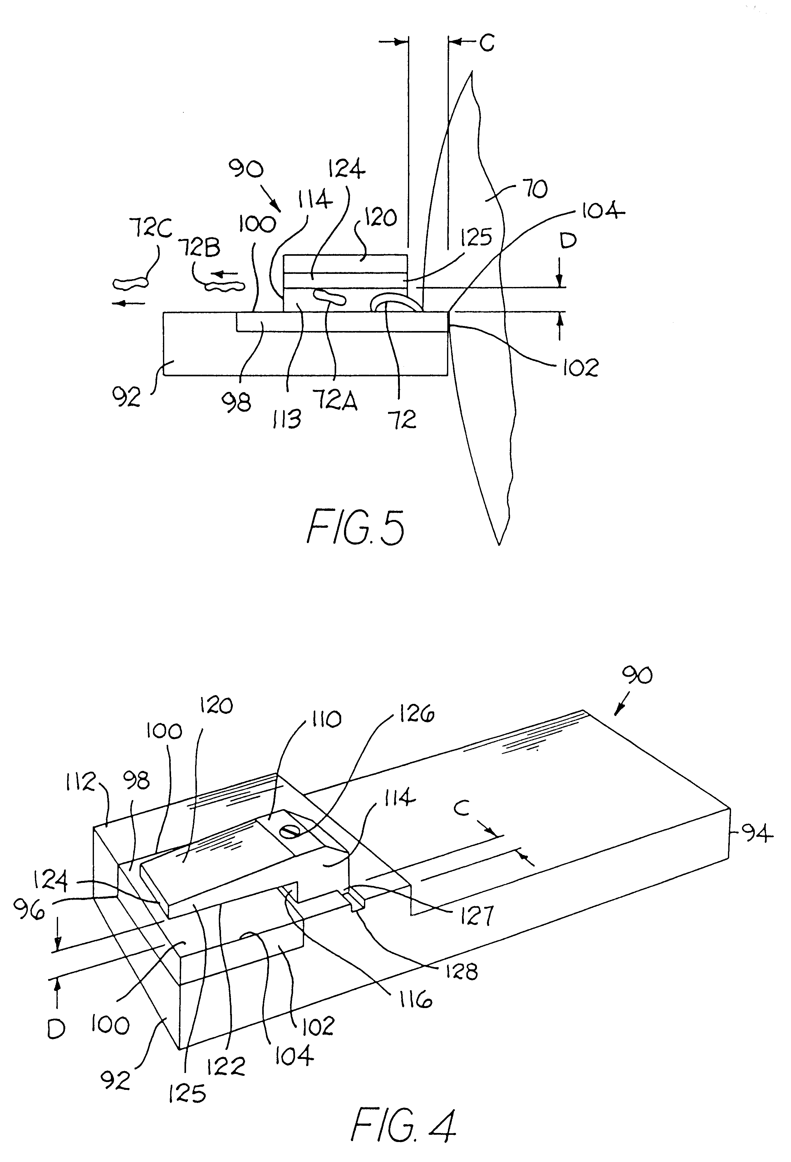
In still another form thereof, the invention is a method of removing metal from a workpiece using a cutting insert assembly comprising the steps of: providing a workpiece; providing a cutting insert assembly wherein the cutting insert assembly comprises a holder containing a pocket, and a cutting insert having a rake surface, the cutting insert being contained within the pocket so as to present a cutting edge, and a chipbreaker comprising a plate with a bottom surface, the plate being spaced above the rake surface of the cutting insert a first distance, and a conduit being defined at least in part by the rake surface of the cutting insert and the bottom surface of the chipbreaker plate; moving the workpiece relative to the cutting insert whereby the cutting edge engages the workpiece thereby removing a coil of metal from the workpiece; and the metal coil impacting at least a portion of the chipbreaker thereby breaking the metal coil into smaller segments.

Problems solved by technology

Unfortunately, this long tight curl, i.e., bird's nest, is in the work area and may become entangled with the chuck holding the work piece.
The long tight coil may also become entangled with the lead screw on the lathe and cutting tool assembly.
Such a long tight coil of metal if permitted to exist may decrease the useful life of the cutting tool assembly or damage the surface of the workpiece.
Further, for example, if the machine tool operator must stop the lathe and remove the coil or roll of metal from the vicinity of the workpiece and the cutting tool, there is a loss in production of the machine tool operator which results in an increase in the cost of production of the workpiece.
If there is a long roll or coil of metal in the work area, the work area is less safe for the machine tool operator than if the metal removed from the workpiece is broken into small chips.
Further, if the metal removed from the workpiece is one continuous coil or stringer, the metal is not useful for being recycled and melted in a furnace.
If the chips are not baled, the chips burn and vaporize and the metal is lost.
Curling of the coil causes it to work harden, and thus, break into a short segment (or chip) shortly after curling.

Method used


Image

  • Detachable chipbreaker for a cutting insert
  • Detachable chipbreaker for a cutting insert
  • Detachable chipbreaker for a cutting insert

Examples


Embodiment Construction

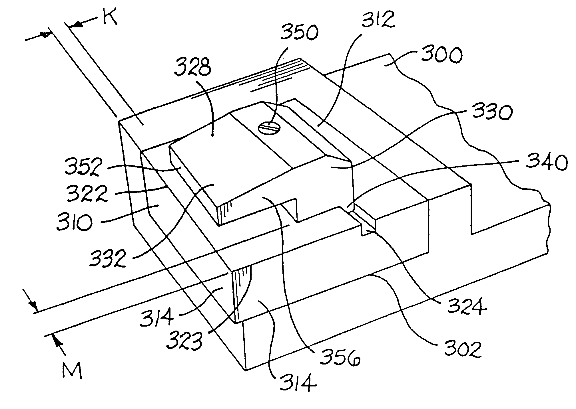
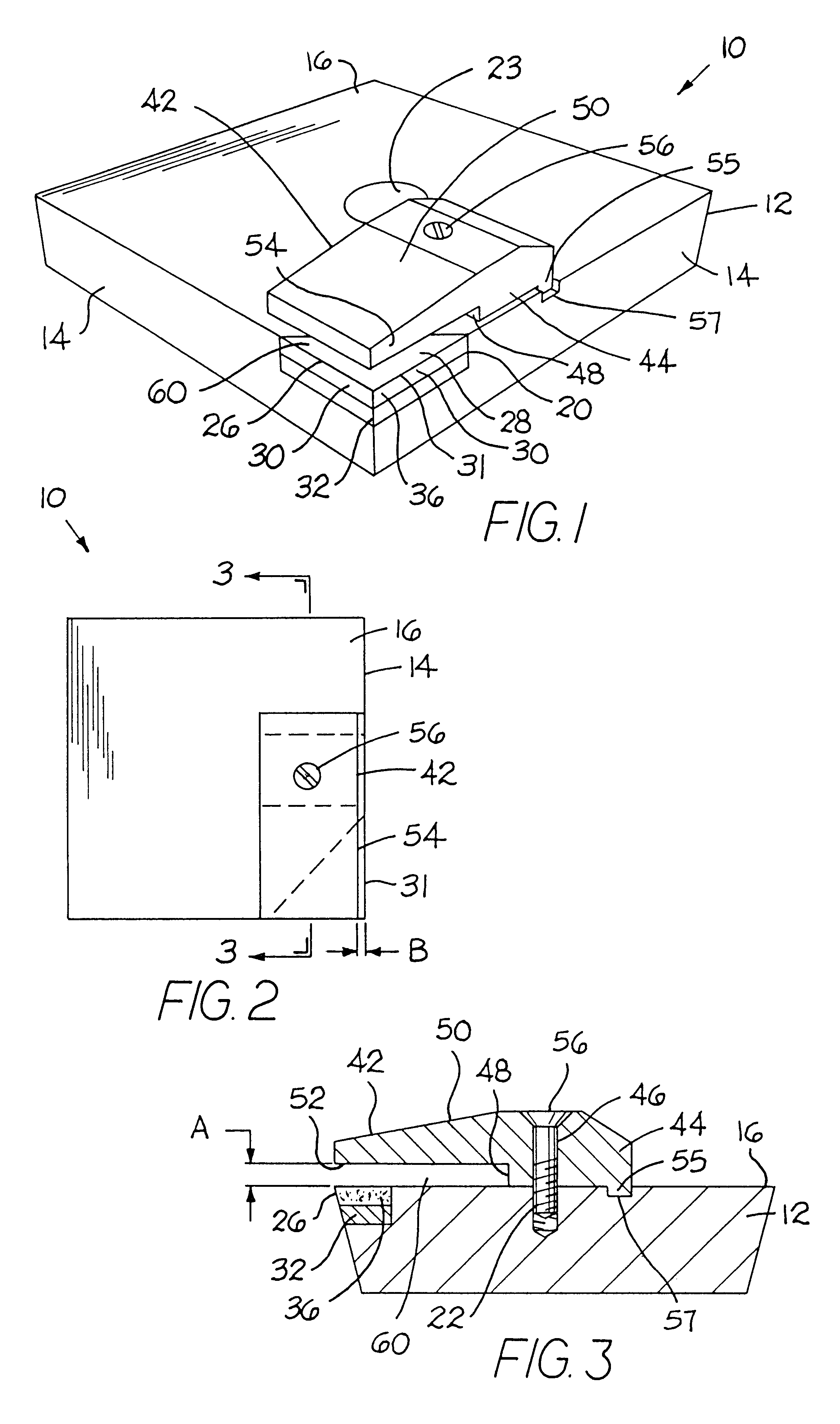
Referring to the drawings there is illustrated a polycrystalline diamond (PCD) composite cutting insert generally designated as 10. Although the cutting insert 10 is illustrated as a PCD cutting insert, it should be appreciated that the cutting insert may be a polycrystalline cubic boron (PCBN} type of insert or a ceramic cutting insert (e.g., an alumina-based cutting insert or a silicon nitride-based cutting insert), a cermet cutting insert (e.g., titanium carbide-based cermet or a titanium carbonitride-based cermet) or a coated (or uncoated) cemented carbide cutting insert. Different cutting insert materials are set forth in U.S. Pat. No. 5,704,734 to Ashley et al. for a Metal Cutting Tool Assembly Having an Automatically Adjustable Chipbreaker wherein this patent is hereby incorporated by reference herein.

Cutting insert 10 includes a cutting insert base 12 generally made out of cemented tungsten carbide. Cutting insert base 12 has a rake surface 16 and flank surfaces 14. At one c...


PUM

PropertyMeasurementUnit
temperatureaaaaaaaaaa
distanceaaaaaaaaaa
surface roughnessaaaaaaaaaa

Abstract

A cutting insert which includes a holder that contains a pocket and a hard insert that has a rake surface. The hard insert is contained within the pocket so as to present a cutting edge. The cutting insert also includes a chipbreaker which comprises a plate with a bottom surface. The chipbreaker is attached to the cutting insert (or optionally to the holder) so that the plate is spaced above the rake surface of the hard insert a first distance forming a conduit for passage of the chips away from the cutting insert. The conduit is defined at least in part by the rake surface of the cutting insert and the bottom surface of the chipbreaker plate.

Description

BACKGROUNDThe invention pertains to a chipbreaker for use in conjunction with a metal cutting insert, as well as the combination of the chipbreaker and the metalcutting insertA cutting tool assembly for metal working (e.g., turning, milling and boring applications) typically comprises a shank, a head portion and one or more cutting inserts. The workpiece or cutting tool assembly is rotated in a chuck. The cutting insert contacts the workpiece and a part of the workpiece is generally removed as rolls, coils or stringers of metal. Sometimes, the roll or stringer of metal will not break so as to become very long, and possibly, become tangled together. Such a long coil is known in this art as a bird's nest. Unfortunately, this long tight curl, i.e., bird's nest, is in the work area and may become entangled with the chuck holding the work piece. The long tight coil may also become entangled with the lead screw on the lathe and cutting tool assembly. Such a long tight coil of metal if per...

Claims


Application Information

Patent Timeline
Patent Type & Authority Patents(United States)
IPC IPC(8): B23B27/16B23B27/22
CPCB23B27/1674Y10T407/112Y10T407/24Y10T407/11Y10T82/24Y10T407/118Y10T82/10
Inventor OLES, EDWARD J.PRIZZI, JOHN J.
Owner KENNAMETAL PC INC
Learn More