Mills for wellbore operations

a milling and wellbore technology, applied in the direction of borehole/well accessories, drilling pipes, drilling rods, etc., can solve the problems of difficult verification of adhesion quality, unsatisfactory cracks, and limited carbide selection

Inactive Publication Date: 2001-01-09
WEATHERFORD TECH HLDG LLC
View PDF135 Cites 78 Cited by
  • Summary
  • Abstract
  • Description
  • Claims
  • Application Information

AI Technical Summary

Benefits of technology

The present invention, in at least certain embodiments, discloses a wellbore mill having a mill body and a plurality of cutting elements or milling inserts mechanically secured in corresponding holes or recesses in the mill body. Such a mill may be any known wellbore mill, including, but not limited to, window mills, starting mills, watermelon mills, pilot mills, section mills, and junk mills. In certain aspects, the inserts are all substantially the same and protrude substantially the same distance out from the mill body. In other aspects, any or all of these parameters differ for different inserts of the plurality of inserts: diameter, length, shape, specific insert material, and depth of securement in the mill body. For example, and not by way of limitation, inserts shapes, viewed e.g. from above, may be circular, elliptical, square, triangular, trapezoidal, rectangular, pentagonal, hexagonal, etc.

Problems solved by technology

A variety of problems are associated with efforts to braze or weld inserts onto milling tools.
When welding methods are used undesirable temperature-induced changes to a base metal or to an insert may result.
Variations in thermal coefficients of expansion between materials e.g. between carbides and bonding materials, can result in undesirable cracks during cooling.
Verification of adhesion quality is difficult.
If brazing is employed, carbide selection may be limited, e.g. possibly coated carbides may not be usable.
With certain welding methods inserts are not precisely located and are placed inconsistently.

Method used


Image

  • Mills for wellbore operations
  • Mills for wellbore operations
  • Mills for wellbore operations

Examples


Embodiment Construction

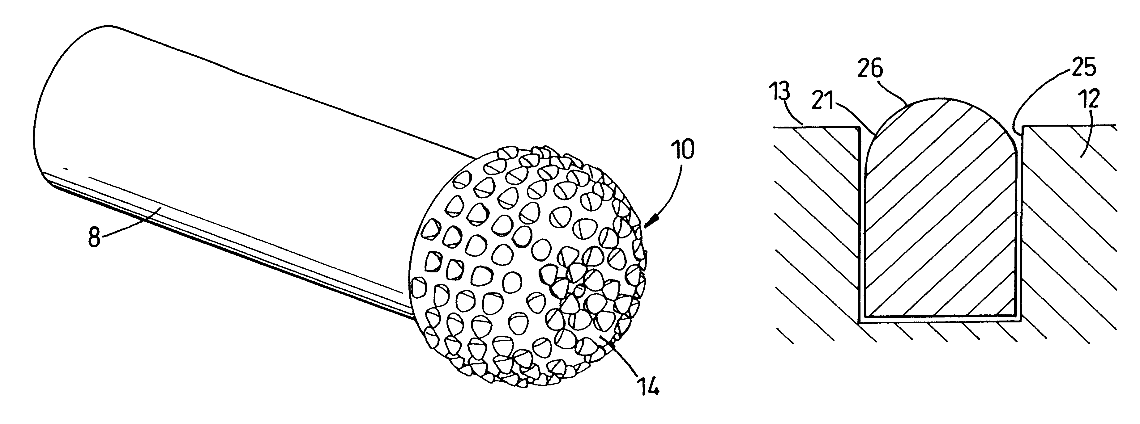
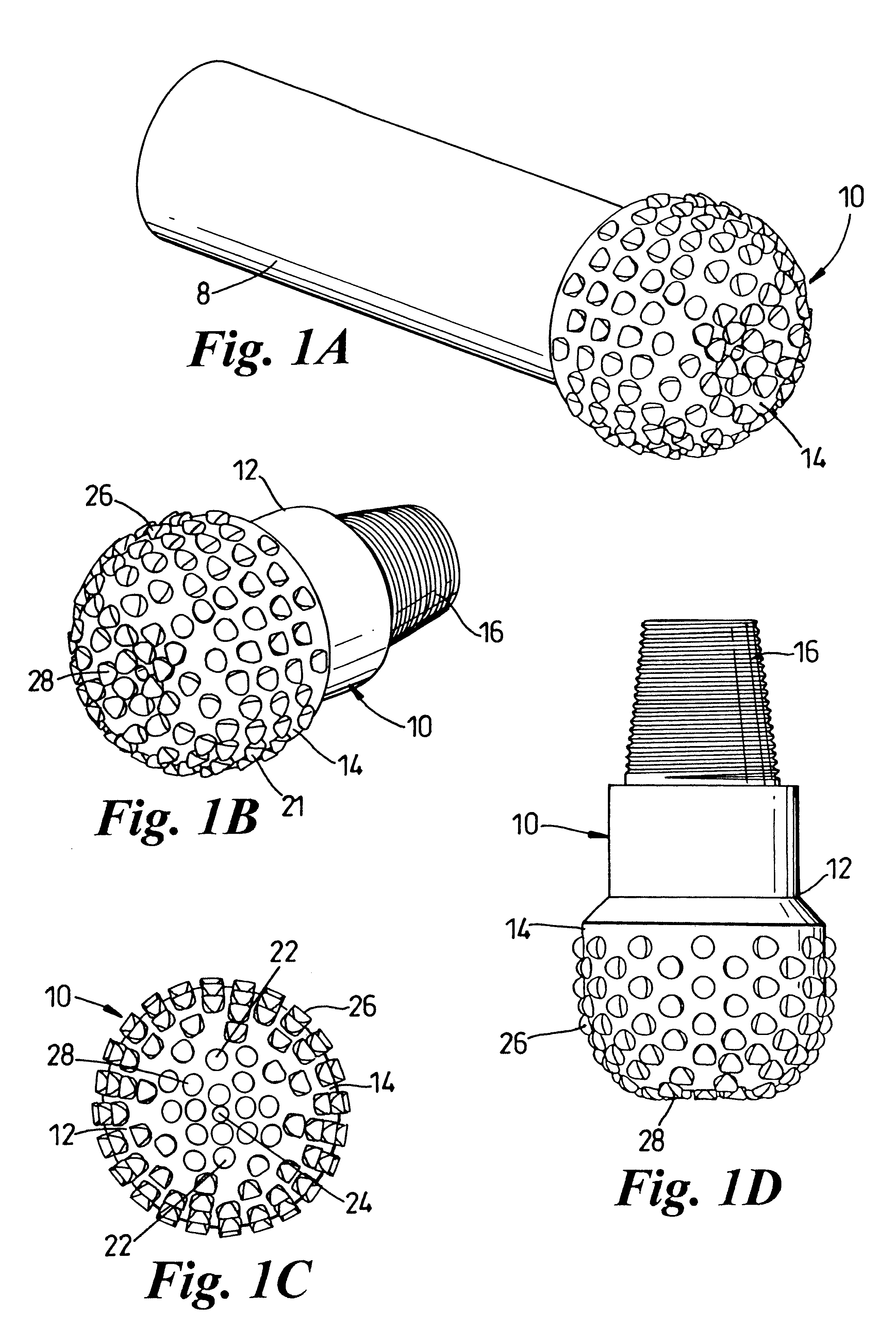
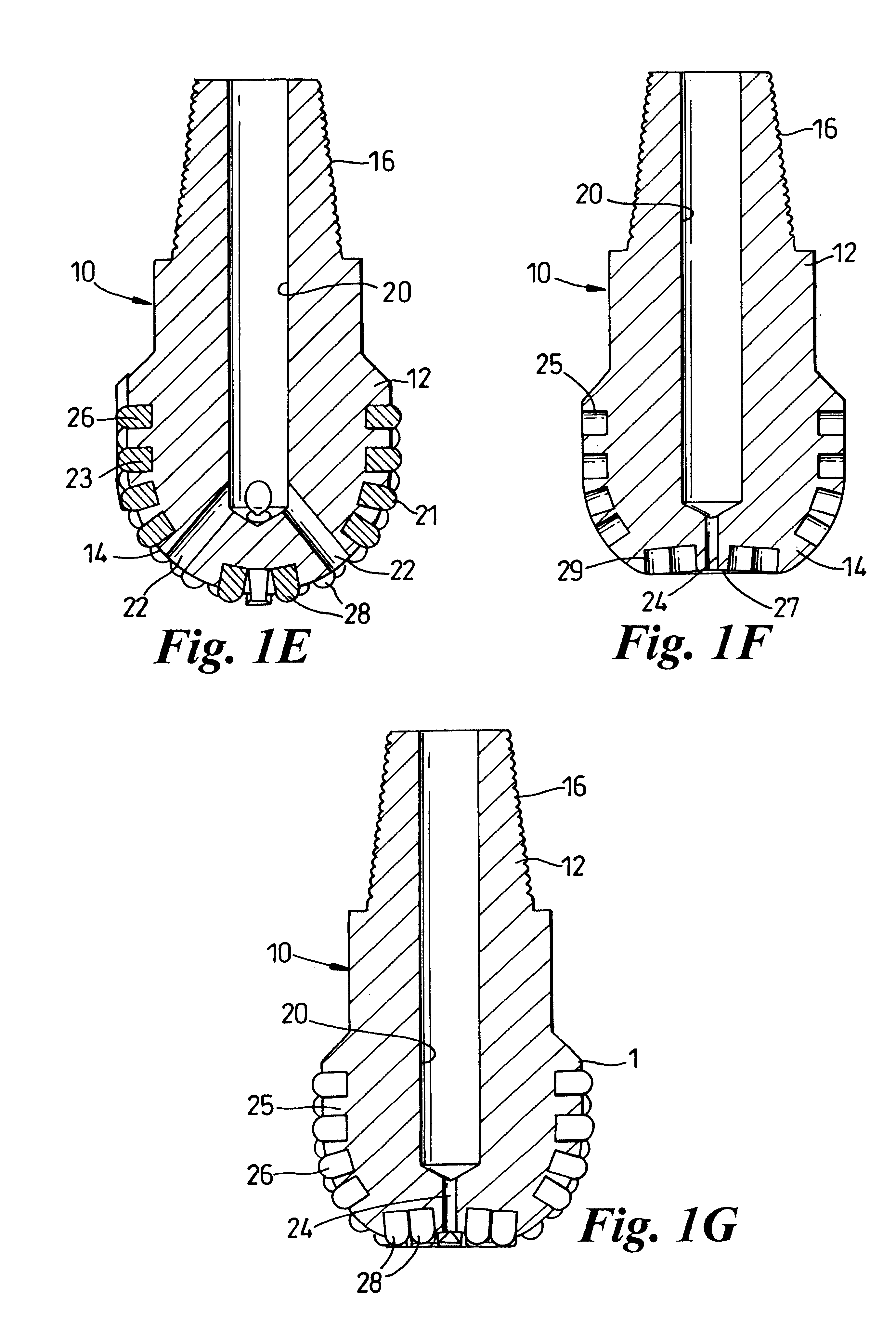
FIGS. 1A-1G show a mill 10 according to the present invention with a mill body 12 having a lower enlarged bulb 14 and an upper threaded connector 16 for threadedly connecting the mill 10 to a correspondingly threaded tubular 8 which may in turn be connected to a tubular string (not shown) run down into an earth wellbore. The tubular 8 and the tubular string have fluid flow bores for directing fluid pumped from the earth surface under pressure to a fluid flow bore 20 of the mill 10.

A plurality of side ports 22 and a central port 24 are in fluid communication with the flow bore 20 so that fluid may be jetted therefrom to facilitate milling, cooling, and the movement of milled cuttings and debris away from the mill 10.

The bulb 14 of the mill 10 has a plurality of side recesses 25 into which are press fit a plurality of corresponding side inserts 26. The lower end of the bulb 14 has a slightly indented central portion 27 and a plurality of end inserts 28 press fit in corresponding reces...


PUM


Abstract

A wellbore mill has been invented that, in certain aspects, has a body having a top and a bottom and, optionally, a fluid flow channel extending therethrough from top to bottom with, optionally, one or more fluid jetting ports in fluid communication with the fluid flow channel, milling apparatus on the body including a plurality of milling inserts, each insert mechanically secured in a corresponding recess in the body, said mechanical securement sufficient for effective milling in a wellbore. A wellbore milling method for milling an opening in a selected tubular of a tubular string in a wellbore has been invented that includes installing and using such a mill.

Description

1. Field of the InventionThis invention is related to wellbore mills, wellbore milling processes, milling tools and whipstocks; and in one aspect to milling processes which employ a diverter or a whipstock. Various milling methods and systems are disclosed.2. Description of Related ArtIn wellbore operations, milling tools are used to cut out windows or pockets from a tubular, e.g. for directional drilling and sidetracking; and to remove materials downhole in a well bore, such as pipe, casing, casing liners, tubing, or jammed tools. Many wellbore milling tools have a plurality of cutting elements or "inserts" secured to milling blades and / or milling surfaces. Typically these inserts are fixed on the blades by brazing or welding. In certain prior art mills, holes are provided into which part of the insert is inserted and by which the insert is held in place prior to brazing or welding.A variety of problems are associated with efforts to braze or weld inserts onto milling tools. Many t...

Claims


Application Information

Patent Timeline
Patent Type & Authority Patents(United States)
IPC IPC(8): E21B17/00E21B29/00E21B17/10E21B29/06E21B10/46E21B10/56E21B10/567E21B10/573
CPCE21B10/46E21B10/5673E21B10/573E21B17/1092E21B29/00E21B29/002E21B29/06
Inventor BRUNNERT, DAVID JOSEPHHART, SHANE PAULBAILEY, THOMAS FHENSON, MICHAEL W.HAUGEN, DAVID MCARTER, THURMAN BMCCLUNG, III, GUY LAMONTE
Owner WEATHERFORD TECH HLDG LLC
Why Eureka
Try Eureka