Switch cabinet with an assembly unit

a technology of assembly unit and switch cabinet, which is applied in the field of switch cabinet, can solve the problems of requiring a large amount of parts and labor

Inactive Publication Date: 2001-01-09
RITTALWERK RUDOLF LOH GMBH & CO KG
View PDF16 Cites 31 Cited by
  • Summary
  • Abstract
  • Description
  • Claims
  • Application Information

AI Technical Summary

Problems solved by technology

For making ready the mounting plate and the flanges on which the glide elements are guided, considerable output of parts and labor is required.

Method used


Image

  • Switch cabinet with an assembly unit
  • Switch cabinet with an assembly unit

Examples


Embodiment Construction

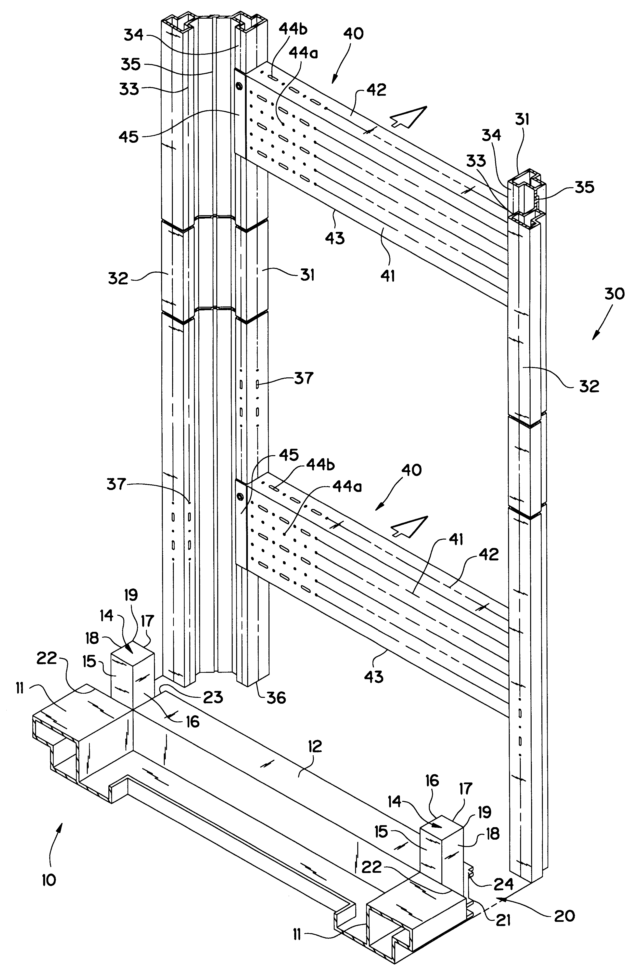
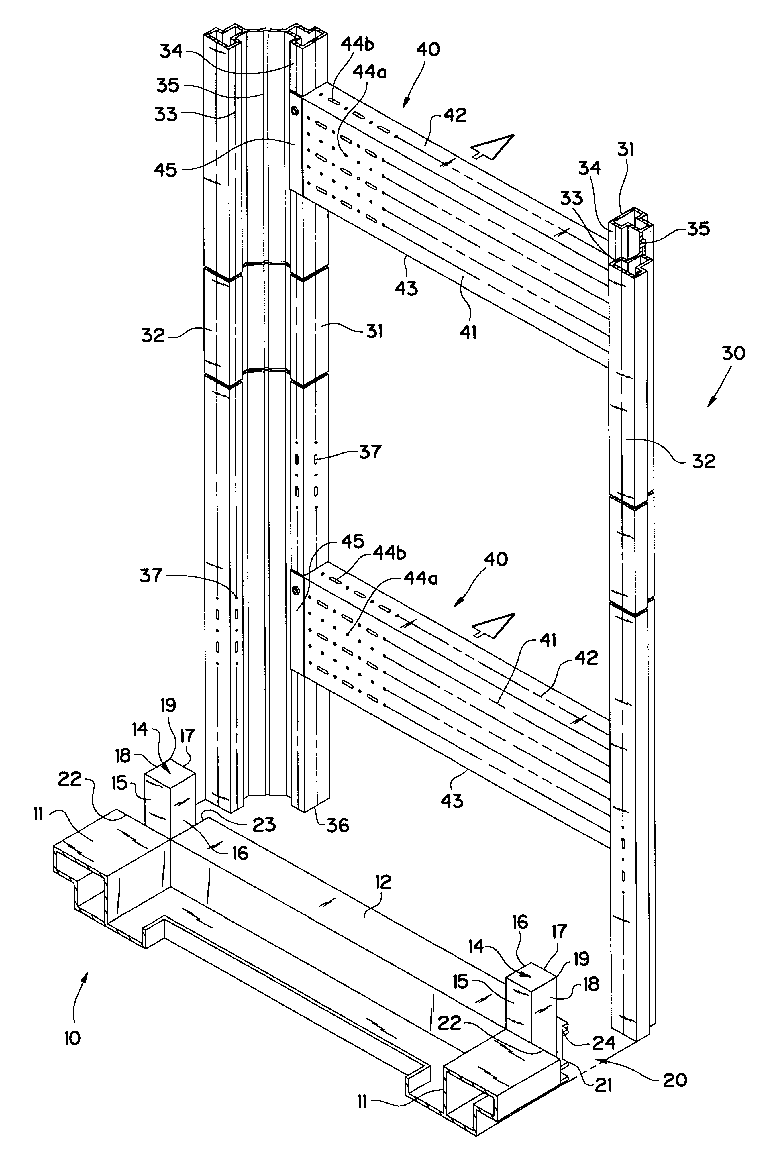
A lower unit (10) is constructed from horizontal depth and longitudinal struts (11 and 12) equal in cross-section and connected with each other at their ends, so that a closed frame is created. In corner areas of the lower unit (10) receiving elements (20), which are open to the outside, are formed into which corner connectors (14) are placed. The corner connectors (14) are in a form of cuboid elements which are placed onto a plate-like projection (24) constructed as a floor surface. The plate-like projection (24) is connected in one piece with the lower unit (10). The corner connector (14) forms contact surfaces (15 and 16) at two sides which correspond to the longitudinal and depth struts (11 and 12). With the contact surfaces (15 and 16), the corner connector (14) is placed flush with the front faces of the longitudinal and depth struts (11 and 12). The corner connector (14) is welded to the lower unit (10). Here, welding seams extend along the contact surfaces (15 and 16) in an ...


PUM


Abstract

A switch cabinet having a rack with vertical frame pieces, wherein the vertical frame pieces are coupled to a lower unit or to an upper unit. Electronic components can be assembled by connecting two adjacent vertical frame pieces to a separate assembly unit with connecting elements and by fixing the components to be assembled.

Description

1. Field of the InventionThis invention relates to a switch cabinet with a rack having vertical frame pieces coupled to a lower unit or an upper unit.2. Description of Prior ArtIn switch cabinets, electronic components or assemblies are secured. For the attachment of these parts, a mounting plate is used. The mounting plate is placed parallel to a rear wall of the switch cabinet and is fixed at the lower unit or the upper unit.Such a switch cabinet is known, for example, from German Patent Reference DE 41 40 072 A1. For this purpose, flanges are molded onto the lower unit. The flanges extend in a direction of the depth of the switch cabinet and accommodate glide elements made of a synthetic material. The glide elements carry the mounting plate. The mounting plate may have components and be wired outside the switch cabinet. Subsequently, the mounting plate with its glide elements is passed through an open front of the switch cabinet and placed onto the flanges. On the flanges, the mo...

Claims


Application Information

Patent Timeline
Patent Type & Authority Patents(United States)
IPC IPC(8): H02B1/32H02B1/00H02B1/01H02B1/30H05K7/18
CPCH02B1/32H02B1/014
Inventor NICOLAI, WALTER
Owner RITTALWERK RUDOLF LOH GMBH & CO KG
Why Eureka
Try Eureka