Light pen

a light pen and light technology, applied in the field of new and improved light pen, can solve the problems of affecting the use of light pens, so as to improve durability, improve durability, and be less costly to operate.

Inactive Publication Date: 2001-01-09
NCR CORP
View PDF6 Cites 22 Cited by
  • Summary
  • Abstract
  • Description
  • Claims
  • Application Information

AI Technical Summary

Benefits of technology

It is a further object of the present invention to provide a "cordless" light pen which does not require a battery.
It is yet another object of the present invention to provide a light pen which is light weight, mobile and has improved durability.
It is yet a further object of the present invention to provide a light pen which is less costly to operate than those of the prior art.
It is still another object of the present invention to provide a light pen which eliminates the "down time" experienced by known light pens.
It is still a further object of the present invention to provide a light pen which does not require electrical connections and relatively fragile components.
It is another object of the present invention to provide a light pen having improved mechanical strength, and thus resistance to accidental damage.

Problems solved by technology

The light source for known light pens disadvantageously comprises a relatively fragile lamp or L.E.D. which can readily suffer damage if the pen is dropped.
The power is supplied by way of electrical connections which may also be fragile and prone to breakage if the pen is dropped or otherwise misused.
Such components are generally expensive to purchase and assemble.
However, known cordless light pens suffer particular disadvantages in that a battery must be provided for its use, which increases the operating cost of such pens.
If a replaceable battery is used, this further increases the cost and also makes operation of the pen dependent on the availability of a replacement battery.
If a re-chargeable battery is employed this may also lead to an increase in the "down time" for the pen, i.e. the period during which the pen can not be used.

Method used


Image

  • Light pen
  • Light pen
  • Light pen

Examples


Embodiment Construction

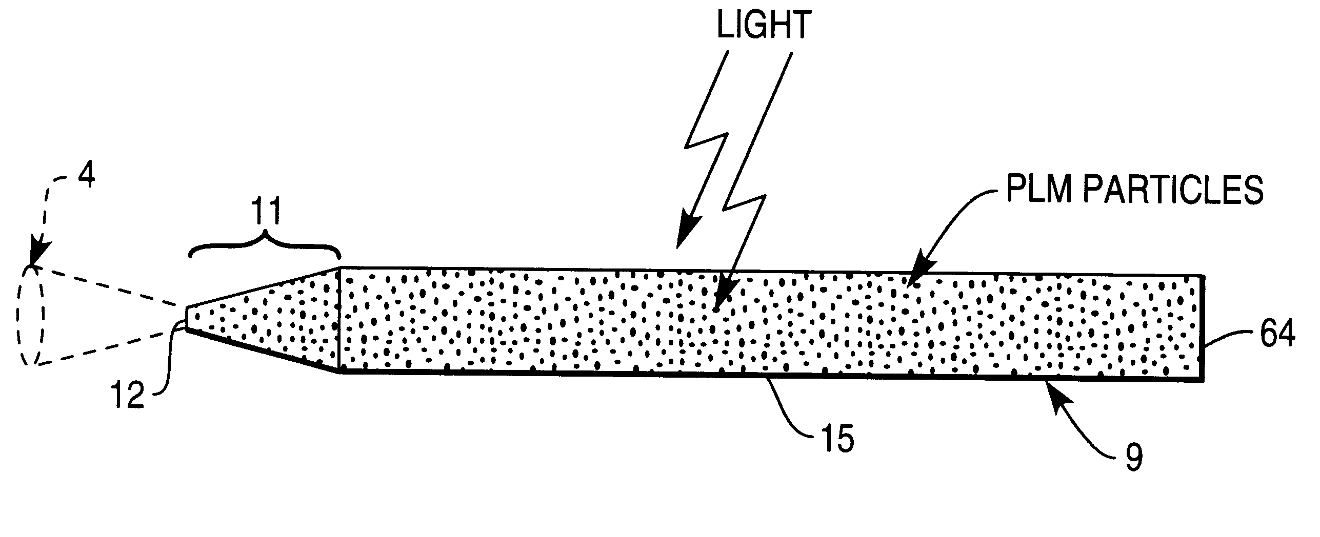
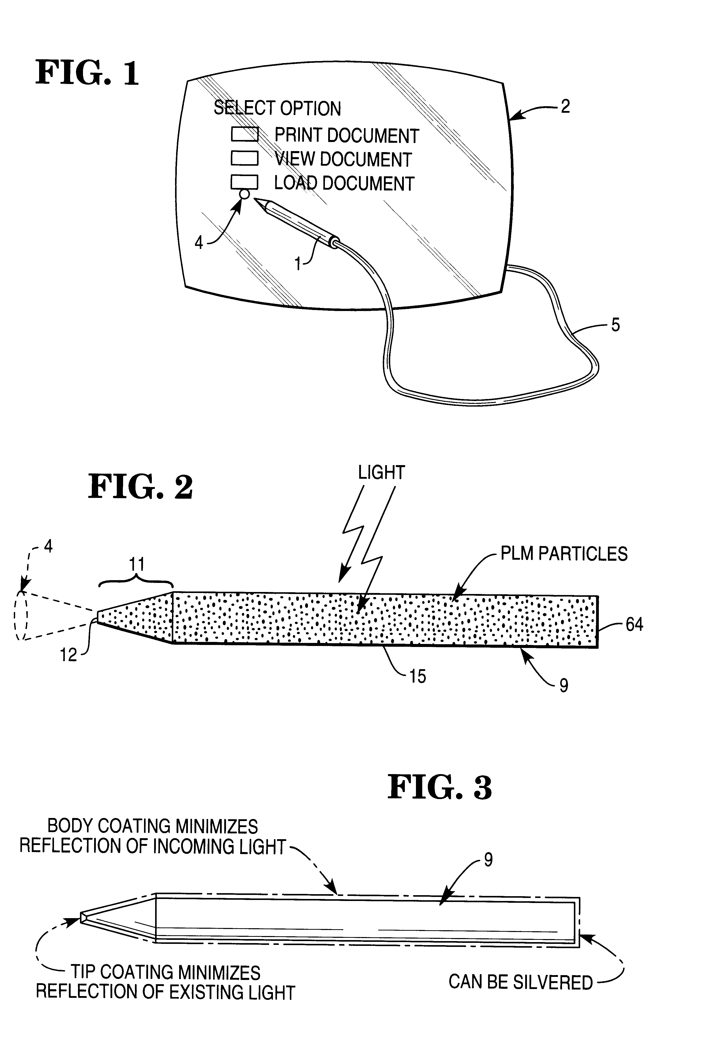
One type of known light pen is shown in FIG. 1. The pen 1 illuminates a spot 4, thereby allowing a computer to obtain data from the pen, based on the position of the spot. For example, the display may show a series of boxes, as indicated, each of which indicates a different option for the user to select. The user selects an option by placing the spot of light into the proper box. The display detects which box contains the light spot, and thus recognizes the choice made by the user.

FIG. 2 shows a light pen according to one form of the present invention. The light pen includes a rod 9, constructed of a transparent material, polymethyl methacrylate (PMMA), containing particles of a photoluminescent material (PLM). The PLM absorbs ambient light, as indicated. The absorption promotes electrons in the PLM to higher energy states which then fall to lower states, causing the PLM to radiate light. Part of the radiated light is reflected internally at the interface between the rod 9 and air s...


PUM


Abstract

A light pen for a computer having an elongated body member which contains a photoluminescent material (PLM). The PLM absorbs ambient light of one wavelength, and radiates light of another wavelength in response. The radiated light is directed so as to be projected from a tip of the light pen as required.

Description

The present invention relates to a pen-like device having a light output, hereinafter referred to as a light pen.Light pens are commonly used as input devices for data processing and storage systems in place of conventional keyboards and mouse devices. A light pen is used in combination with a display screen incorporating a photosensitive digitizer or photosensitive sheet material. As such, information can be input by writing with the light pen on the screen and typically the screen displays the instantaneous position, and path of movement, of the pen. In this way, the screen displays the pattern, e.g. a written message, sketch or signature traced thereon.The light source for known light pens disadvantageously comprises a relatively fragile lamp or L.E.D. which can readily suffer damage if the pen is dropped. The light source is powered either by way of a power supply cord or cable or by way of a battery if a "cordless" light pen is required. The power is supplied by way of electric...

Claims


Application Information

Patent Timeline
Patent Type & Authority Patents(United States)
IPC IPC(8): G06F3/033G06F3/041
CPCG06F3/03542
Inventor BAUR, PETER F.
Owner NCR CORP
Why Eureka
Try Eureka