Stencil printing machine and stencil printing drum

a printing machine and stencil technology, applied in printing presses, office printing, printing, etc., can solve the problems of increased printing pressure on the center of the opening portion 104, insufficient printing pressure on both end-portions of the printing drum, and indistinct images formed ther

Inactive Publication Date: 2001-01-16
RISO KAGAKU CORP
View PDF9 Cites 34 Cited by
  • Summary
  • Abstract
  • Description
  • Claims
  • Application Information

AI Technical Summary

Problems solved by technology

Therefore, printing pressures exerted on both end-portions of the printing drum may be not enough and images formed there may be indistinct.
This seems to be due to insufficient ink transferring onto the printing sheet at both end-portions of the printing drum in the axial

Method used


Image

  • Stencil printing machine and stencil printing drum
  • Stencil printing machine and stencil printing drum
  • Stencil printing machine and stencil printing drum

Examples


first embodiment

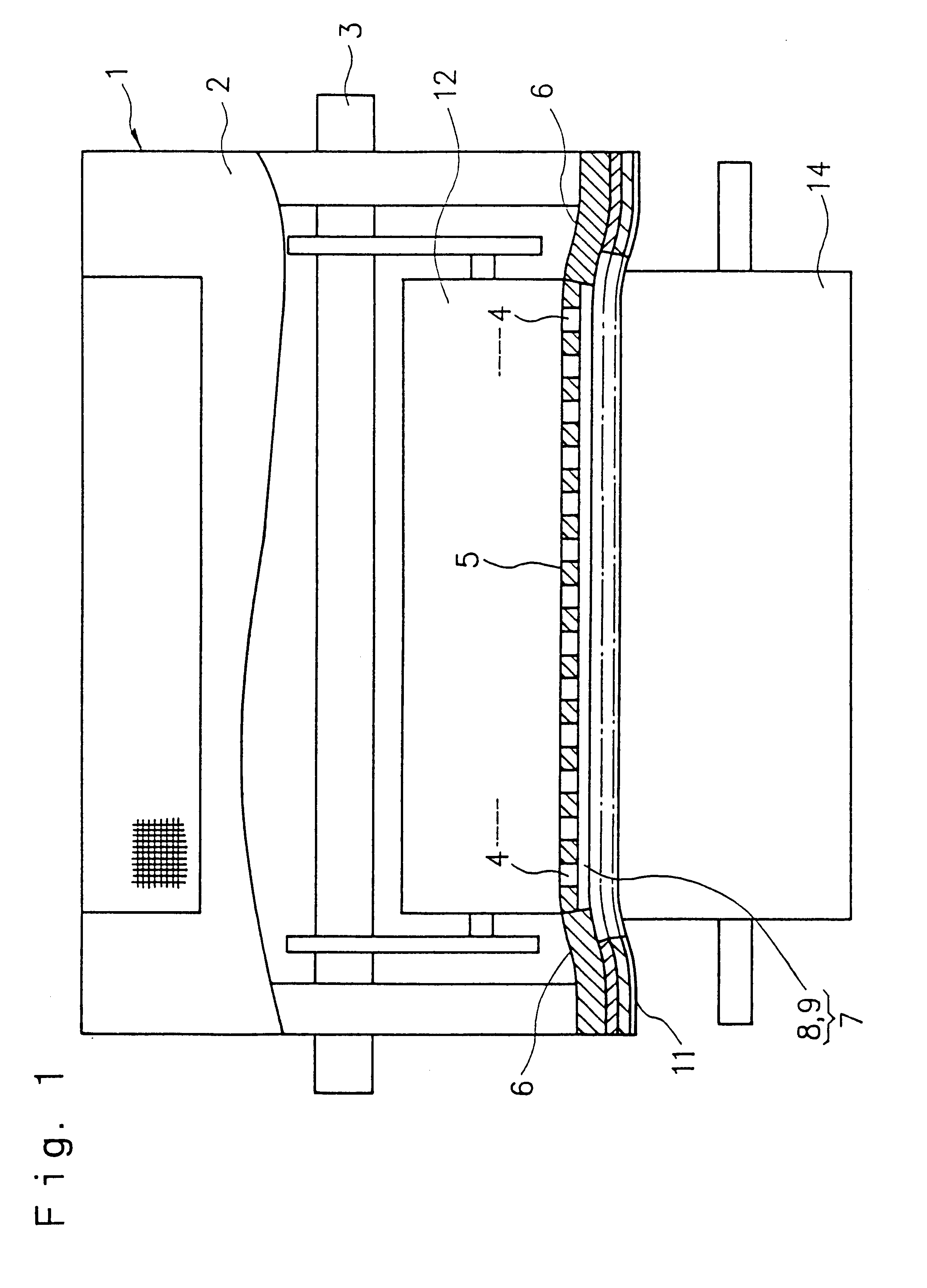
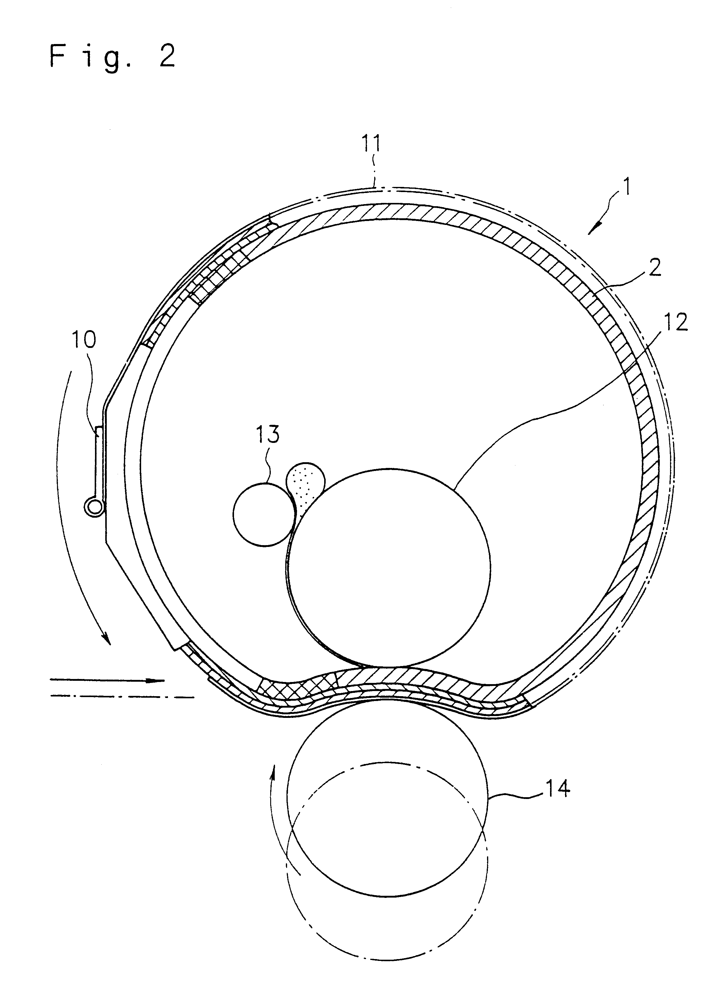
A first embodiment will be explained referring to FIGS. 1 to 3.

A printing drum 1 has a cylindrical circumferential wall 2. The printing drum 1 is supported on a shaft 3 to be driven to rotate by driving means (not shown). As illustrated in FIG. 3, there are formed an opening portion 5 (printing area) and a non-opening portion 6 (non-printing area) in the circumferential wall 2. The opening portion 5 has many through holes 4 formed therein, and the non-opening portion is formed around the opening portion 5.

As illustrated in FIG. 1 and FIG. 3, the through holes 4 are each circular, and formed to be arranged at a predetermined distance therebetween. A recessed portion 7 is formed in the opening portion 5 on an outer circumferential surface side of the circumferential wall 2. The recessed portion 7 of the present embodiment means a dent or a groove not passing through the circumferential wall 2. Concerning a shape of the recessed portion, arrangement of the recessed portion around the t...

second embodiment

A second embodiment will be explained referring to FIG. 4. As a stencil printing machine, basic constitution of this embodiment is approximately identical to that of the first embodiment. A pattern of a recessed portion in an opening portion 5a of the printing drum is different from the embodiment explained before. In the present embodiment, a pattern of an upper end (a head) and a lower end (a tail) in a rotational direction (1) of the printing drum, which direction is a circumferential direction or printing direction on printing sheet, is arranged to be different from that of another portion. Each recessed portion formed in this head and tail area 15 includes circular recesses respectively communicating through holes 4. In this head and tail area 15, the circular recesses 8 are independent from each other. They are not connected with each other.

According to the present embodiment, areas of a circumferential wall 2a are, in order of decreasing rigidity, the non-opening portion 6, t...

third embodiment

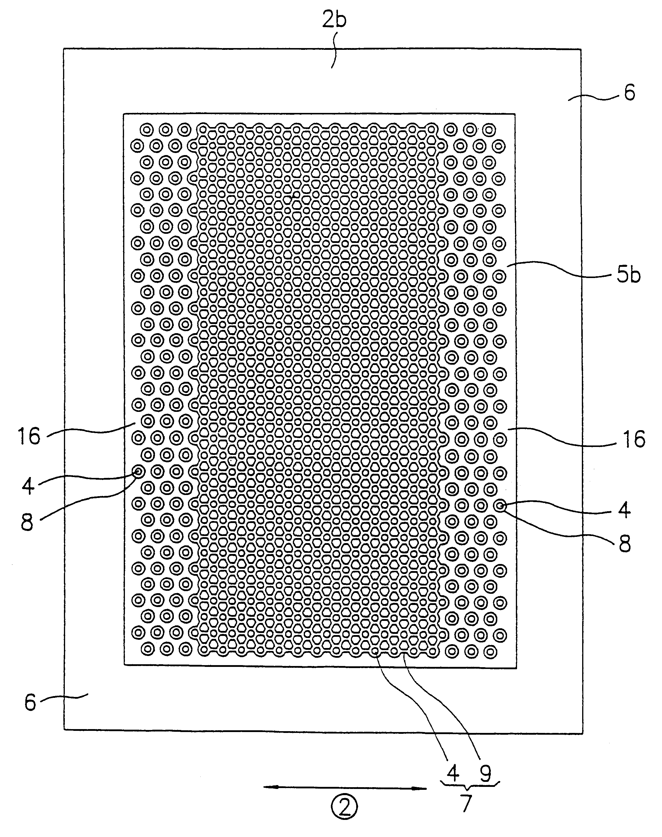
A third embodiment will be explained referring to FIG. 5. As a stencil printing machine, basic constitution of this embodiment is approximately identical to that of the first embodiment. A pattern of a recessed portion in an opening portion 5b of the printing drum is different from the embodiment explained before. In the present embodiment, a medium area 16 is formed in both edge portions of an opening portion 5b (a printing area) adjacent to the non-opening portion 6 in the axial direction (2). Each recessed portion formed in this medium area 16 includes circular recesses respectively communicating through holes 4. In this medium area 16, the circular recesses 8 are independent from each other. They are not connected with each other.

According to the present embodiment, areas of a circumferential wall 2b are, in order of decreasing rigidity, the non-opening portion 6, the medium area 16, and the center of the opening portion 5b. Thus, both the edge portions of the opening portion 5b...


PUM


Abstract

A stencil printing machine has a printing drum having a cylindrical circumferential wall adapted to receive a perforated stencil sheet wrapped on an outer circumferential surface thereof and driven to rotate around a central axis thereof the circumferential wall having an opening portion with many through holes formed therein, a non-opening portion formed around the opening portion, and at least one recessed portion formed in at least one part of the opening portion adjacent to the non-opening portion in an axial direction of the circumferential wall; an ink supplying roller situated in the printing drum for supplying ink to an inner circumferential surface of the cylindrical circumferential wall of the printing drum; and a press roller situated adjacent to the printing drum and being urged against the outer circumferential surface of the cylindrical circumferential wall of the printing drum.

Description

1. Field of the InventionThe present invention relates to a stencil printing machine capable of conducting clear printing, and a printing drum used in the printing machine.2. Description of the Related ArtFIG. 16 and FIG. 17 are sectional views showing a printing section of a conventional stencil printing machine. FIG. 18 is a part of a circumferential wall of a printing drum; an essential portion of said printing section. A printing drum 100 has a circumferential wall 101. The printing drum 100 is rotatably supported by an axis 102 and driven to rotate around the axis by non-illustrated driving means. In the circumferential wall 101, there is formed an opening portion 104 (printing area) having many through holes 103 formed therein and a non-opening portion 105 (non-printing area) formed around said opening portion 104. Clamping means 106 is disposed on the non-opening portion 105 in an outer circumferential surface of the circumferential wall 101. A perforated stencil sheet 107 is...

Claims


Application Information

Patent Timeline
IPC IPC(8): B41L13/06B41L13/04B41L13/18B41L13/00
CPCB41L13/06B41L13/18
Inventor TANAKA, YOSHITAKANEGISHI, HIDEO
Owner RISO KAGAKU CORP
Why Eureka
Try Eureka