
Bumper construction including self-orienting support towers providing consistent energy absorption on impact

a technology of self-orientation and support towers, which is applied in the direction of shock absorbers, elastic dampers, bumpers, etc., can solve the problems of undesirable parallelogram-like collapse of towers and towers experiencing parallelogram-like shearing for

Inactive Publication Date: 2001-01-16
SHAPE CORP
View PDF25 Cites 127 Cited by
  • Summary
  • Abstract
  • Description
  • Claims
  • Application Information

AI Technical Summary

Benefits of technology

In one aspect of the present invention, a bumper system for a vehicle includes a bumper beam including a pair of spaced-apart brackets, and a pair of towers configured to attach to the brackets and to support the bumper beam on a vehicle. A swivel connection connects each tower to an associated one of the brackets. The swivel connection includes a protruding section that is located on one of the bracket and the tower, and a socket is formed on the other of the bracket and the tower for receiving the protruding section, with the protruding section and the socket operably engaging and retained together in a manner causing the tower to self-orient toward the bracket during a catastrophic impact of the bumper beam despite angled and unbalanced impact forces.

Problems solved by technology

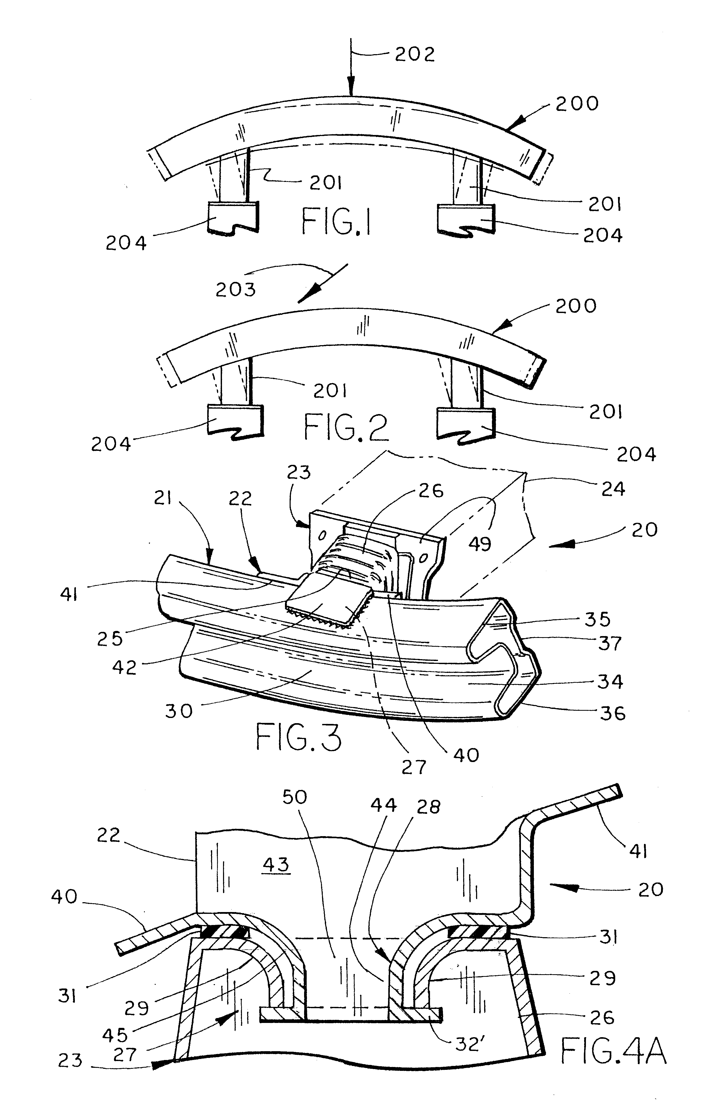
A problem is that when impacted in their center, such as by a force 202, the beams 200 flex toward a straightened position (shown in dashed lines) which causes the towers 201 to shift and tilt outwardly, resulting in the towers experiencing a parallelogram-like shearing force.
The result in both circumstances is that the towers experience torsional forces, causing the towers to want to collapse at least in part with a parallelogram-like motion, with the walls staying basically flat and bending only at their ends.
Parallelogram-like collapse of a tower is undesirable, since a relatively low amount of impact energy is absorbed.

Method used


Image

  • Bumper construction including self-orienting support towers providing consistent energy absorption on impact
  • Bumper construction including self-orienting support towers providing consistent energy absorption on impact
  • Bumper construction including self-orienting support towers providing consistent energy absorption on impact

Examples


Embodiment Construction

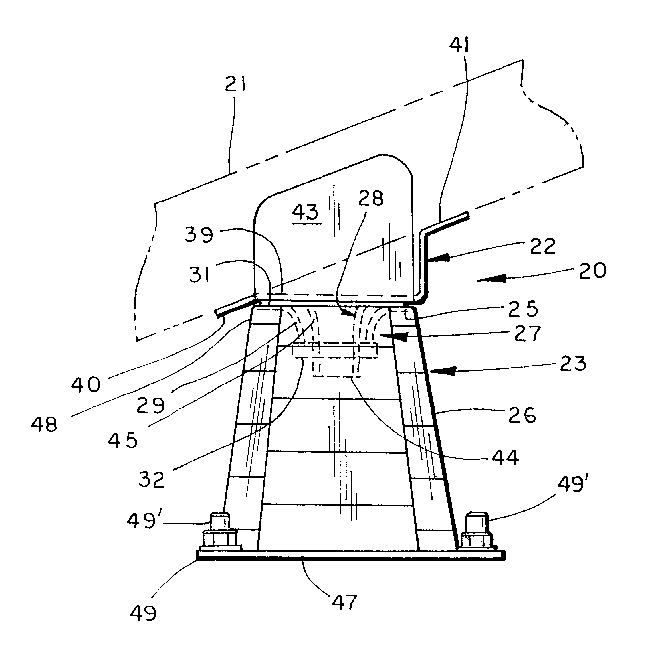
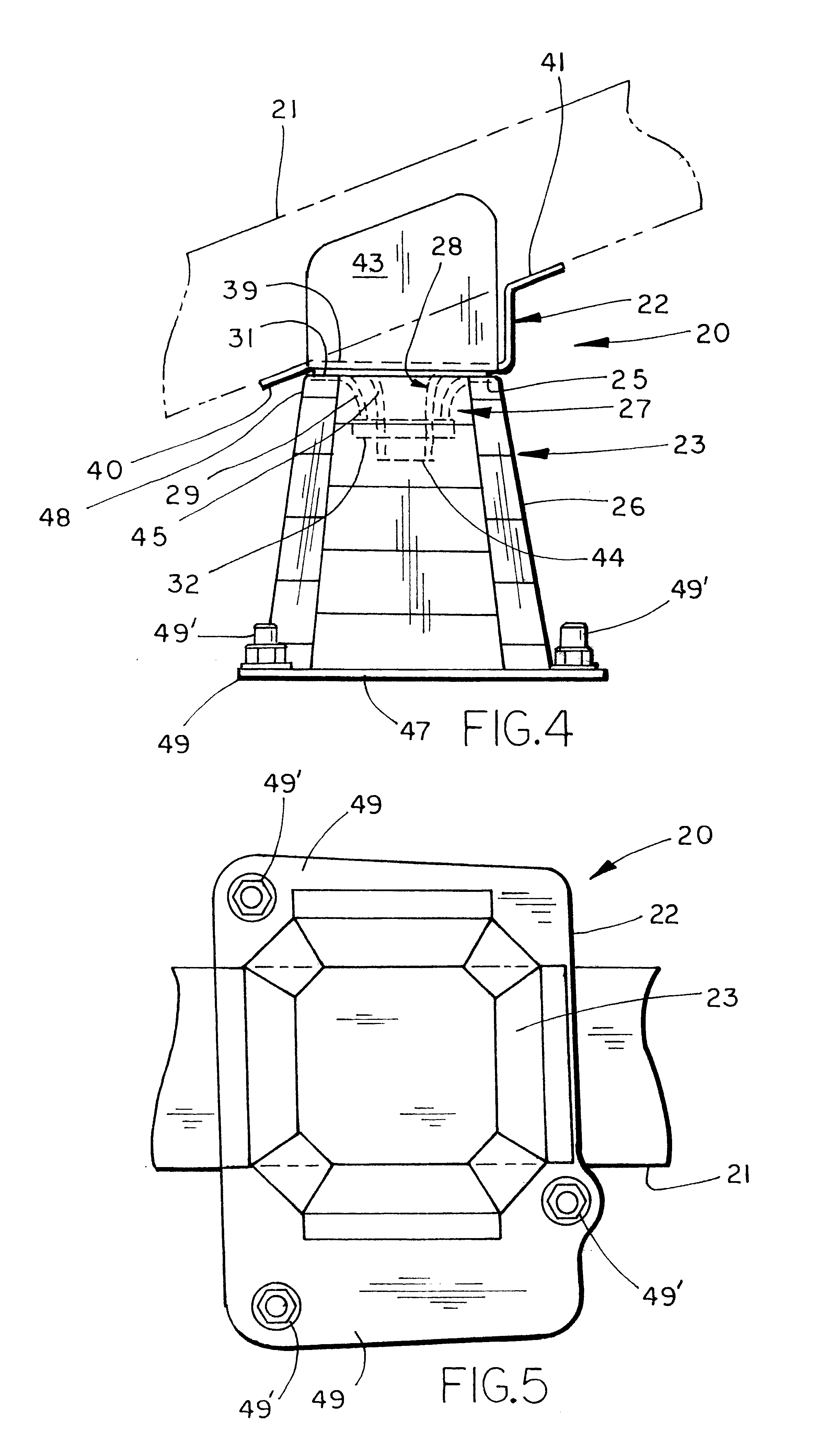
A bumper construction 20 (FIG. 3) for a vehicle includes a swept tubular bumper beam 21 having a pair of spaced-apart brackets 22, and a pair of towers 23 configured to attach to the brackets 22 so as to support the bumper beam 21 on a vehicle frame 24. The towers 23 each include a platform 25 configured for attachment to one of the brackets 22, and further include an elongated tubular portion 26 configured for connection to the vehicle. A swivel connection 27 (FIG. 4) connects each tower 23 to an associated bracket 22. The swivel connections 27 each include a protruding section 28 on the bracket 22 and a socket 29 on the tower 23 that operably receives the protruding section 28. The protruding section 28 and the socket 29 are configured to permit some relative horizontal and vertical rotation at the swivel connection 27, but further are designed to "drag" the tower 23 with the bracket 22 during impact and to orient the tower 23 toward the bracket 22 as the bumper construction 20 be...


PUM


Abstract

A bumper construction for a vehicle includes a swept tubular bumper beam having a pair of spaced-apart brackets and a pair of towers configured to attach to the brackets and support the bumper beam on a vehicle. The towers each include a platform configured for attachment to one of the brackets, and further include an elongated portion configured for connection to the vehicle. A swivel connection connects the tower to the bumper beam. The connection includes a protruding section on one of the bracket and the tower, and a socket receiving the protruding section on the other of the bracket and the tower. The protruding section and the socket are configured to draw the tower toward an impacting force during a catastrophic impact, such that the tower is more likely to crush with a high-energy absorbing, accordion-like collapse (as opposed to a low-energy absorbing parallelogram-like collapse).

Description

The present invention concerns vehicle bumper constructions adapted to provide a consistent front (or rear) impact strength and energy absorption, even where the impact forces are angled relative to a longitudinal centerline of a vehicle. In particular, the present vehicle bumper construction is adapted to provide a more consistent energy absorption during catastrophic front impact, despite the angle or location of engagement by the colliding object.Vehicle bumpers are designed to withstand considerable impact forces and further, where the impact is severe enough to cause damage, are constructed to absorb energy to reduce damage to the vehicle. An important part of the bumper construction includes the vehicle attachment towers that are used to support the bumpers on the vehicle frame. A problem is that the impact forces generated during a vehicle crash are not always centered on the bumper, and further are not always parallel a longitudinal centerline of the vehicle. When imbalanced...

Claims


Application Information

Patent Timeline
IPC IPC(8): B60R19/24B60R19/34B60R21/00B60R19/18
CPCB60R19/34B60R2019/1813B60R2021/0009
Inventor MCKEON, R. CLAYTON
Owner SHAPE CORP
Learn More