Method for manufacturing a gas sensor unit

a sensor unit and gas sensor technology, applied in the field of manufacturing gas sensor units, can solve the problems of solid electrolyte bodies being prone to breakage, prone to breakage, and in the worst case, being broken

Inactive Publication Date: 2001-01-16
DENSO CORP +1
View PDF10 Cites 13 Cited by
  • Summary
  • Abstract
  • Description
  • Claims
  • Application Information

AI Technical Summary

Problems solved by technology

However, this type of zirconia is neither resistant to mechanical shocks such as vibrations, nor resistant to thermal shocks, thus being liable to break.
When using partially stabilized zirconia in an oxygen sensor unit as a solid electrolyte body and subjecting the unit to heating and cooling cycles, this solid electrolyte body may undesirably be cracked or, in the worst case, broken.
In this condition, if phase ...

Method used


Image

  • Method for manufacturing a gas sensor unit
  • Method for manufacturing a gas sensor unit
  • Method for manufacturing a gas sensor unit

Examples


embodiment 1

Reference is now made to FIGS. 1 to 6 to illustrate the method for manufacturing an oxygen sensor unit according to the invention along with its performance being shown in comparison with sensor units for comparison.

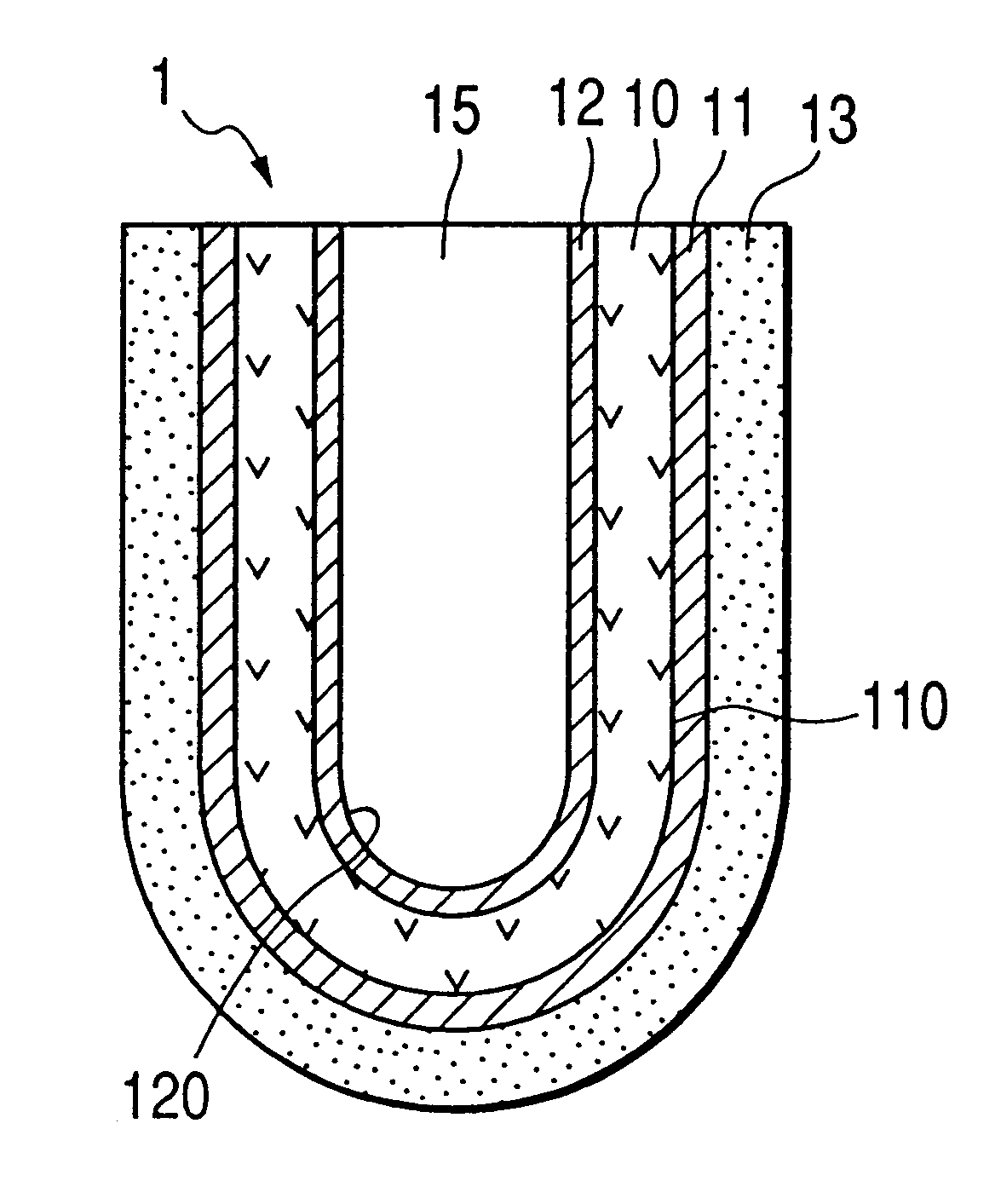
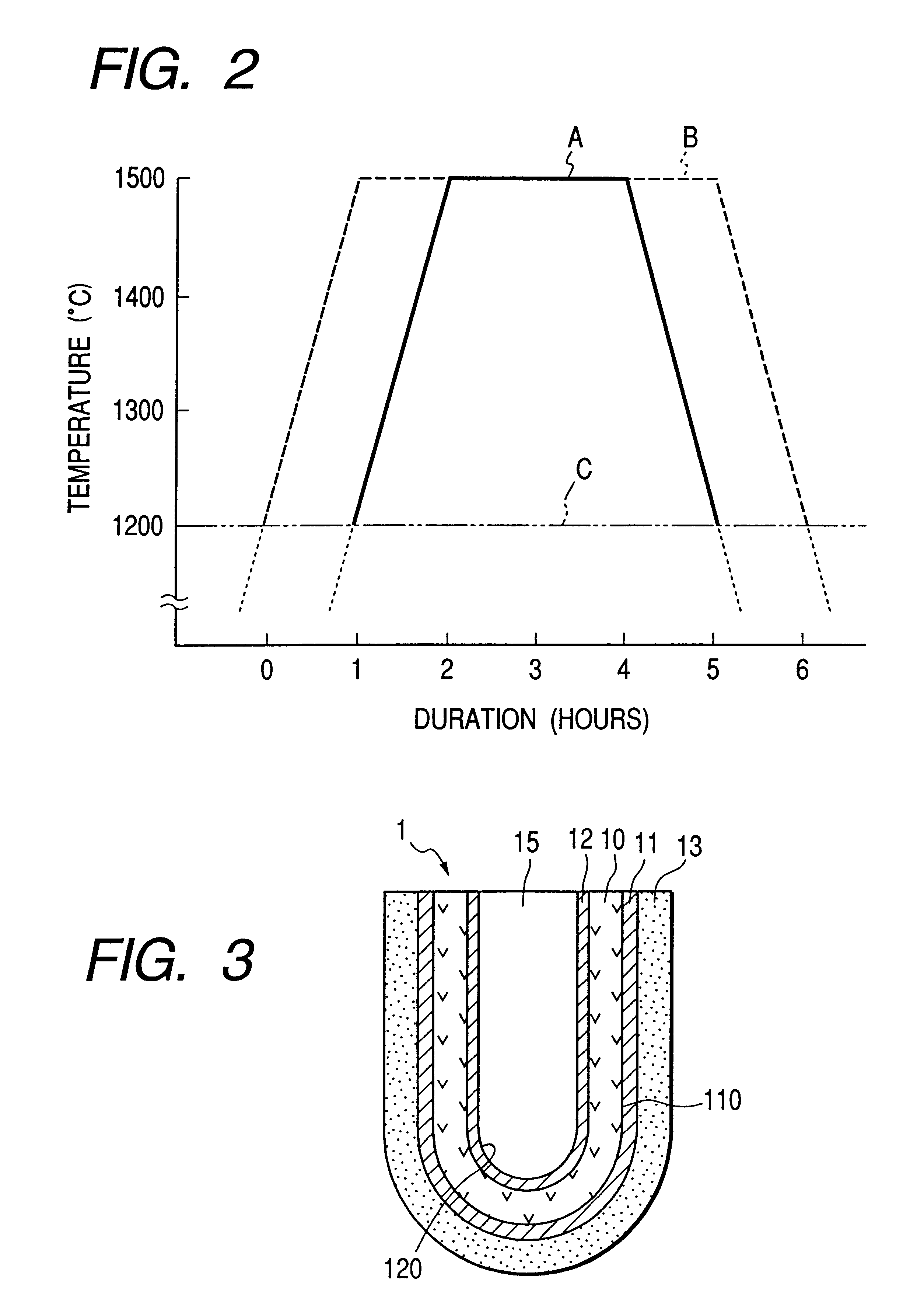
FIG. 3 generally shows an oxygen sensor unit 1 which includes a shaped body 10 of a solid electrolyte having an inner space 15 therein. More particularly, the shaped body 15 is in a U shape in section and may be called a cup-shaped body. The sensor unit 1 includes an inner electrode 12 formed on an inner side 120 of the shaped body 10 and exposed to a reference gas, and an outer electrode 11 formed on an outer side 110 of the shaped body 10 and exposed to a gas to be measured. A porous protective layer 13 is provided to cover the outer electrode 11 and the solid electrolyte 10 in the proximity of the outer electrode 11 therewith.

The solid electrolyte body 10 is made of a sintered product of partially stabilized zirconia which is comprised of zirconia and a stabilizer as ...

embodiment 2

In this embodiment, the general procedure of Embodiment 1 for making the sintered product of partially stabilized zirconia is repeated except that slightly different sintering conditions are used as indicated in Tables 1 to 4, thereby obtaining solid electrolyte body samples. These samples are subjected to several tests to compare their performances with one another.

The tests include measurements of a diffraction intensity ratio and a difference in thermal expansion coefficient, .DELTA..alpha., durability tests described hereinafter wherein it is determined whether or not each solid electrolyte body sample is cracked and broken, and a protective layer associated with the body sample is cracked and separated, and measurement of strength of each solid electrolyte body sample.

The arrangement and the manner of fabrication of sample Nos. 1 to 33 are substantially the same as those described in Embodiment 1. The protective layers of these samples are all formed according to a spray coatin...

embodiment 3

Another embodiment of the invention is described with reference to FIGS. 7 and 8. In these figures, there is shown an oxygen sensor unit 19 having a second protective layer 16 formed on the protective layer 13.

More particularly, as shown in FIG. 7, the oxygen sensor unit 19 of this embodiment is provided with the second protective layer 16 on the surface of the protective layer 13 in order to enhance the trapping effect of harmful components contained in a gas to be measured. The second protective layer 16 is made, for example, of alumina with its thickness at 120 .mu.m and porosity at 20 to 50%.

For the formation of the second protective layer 16, a slurry containing alumina is prepared and coated onto the surface of the protective layer 13 by dipping, followed by thermal treatment of the solid electrolyte body in whole. In this manner, the oxygen sensor unit 19 having the second protective layer 1 is formed.

It will be noted that, as is particularly shown in FIG. 8, the shaped solid...


PUM

PropertyMeasurementUnit
Temperatureaaaaaaaaaa
Timeaaaaaaaaaa
Timeaaaaaaaaaa

Abstract

A method for manufacturing an oxygen sensor unit of the type which includes at least a shaped body of a solid electrolyte, an inner electrode provided on an inside surface of the shaped body and exposed to a reference gas, an outer electrode provided on an outside surface of the shaped body and exposed to a gas to be measured, and a porous protective layer covering the outer electrode and a portion of the shaped body adjoining to said outer electrode wherein the solid electrolyte is made of a mixture of zirconia and a stabilizer therefor and is constituted of a sintered product of partially stabilized zirconia. The method is characterized in that the partially stabilized, sintered zirconia is obtained according to a high temperature sintering process which includes at least the step of sintering the mixture at a temperature of 1200° C. or over for a duration of 2 to 6 hours wherein a value obtained by integrating a variation in the sintering temperature with the duration in the sintering process is in the range of 300 to 1500° C..hour.

Description

1. Field of The InventionThis invention relates to a method for manufacturing an oxygen sensor unit which is suitable for use in oxygen sensors of internal combustion engines for automotive vehicles.2. Description of the Prior ArtFor the control of an air-to-fuel ration in internal combustion engines of automotive vehicles, oxygen sensors have been usually used. A typical structure of such a sensor is, for example, shown in FIG. 4 which will be described hereinafter. An oxygen sensor unit incorporated in the oxygen sensor is, for example, of the type which comprises a solid electrolyte body, and a pair of electrodes formed on inner and outer sides of the solid electrolyte, respectively. Moreover, a protective layer is provided to cover the outer electrode therewith at the outer surface thereof so as to protect the outer electrode from a poisonous contaminant in a gas to be measured as shown in FIG. 3. This figure will also be referred to hereinafter.The solid electrolyte of the oxyg...

Claims


Application Information

Patent Timeline
IPC IPC(8): G01N27/407
CPCG01N27/4073
Inventor KOBAYASHI, KIYOMIMIWA, NAOTOSAITO, TOSHITAKASANO, HIROMIFUJII, NAMITSUGU
Owner DENSO CORP
Why Eureka
Try Eureka