Optical axis correcting apparatus and method of correcting optical axis

a technology of optical axis and correcting apparatus, which is applied in the direction of optical elements, instruments, transmission monitoring, etc., can solve the problems of large-scale construction, troublesome procedure of both methods, and limitation of the number of circuits,

Inactive Publication Date: 2001-01-16
SONY CORP
View PDF5 Cites 41 Cited by
  • Summary
  • Abstract
  • Description
  • Claims
  • Application Information

AI Technical Summary

Problems solved by technology

However, both methods require troublesome procedure and large-scale construction.
On the other hand, to transmit data from the transmitting side to the receiving side by radio, a prescribed frequency band must be allocated out of a limited electric wave source, and realizing it is difficult because practically there is limitation in the number of circuits.
However, an optical space transmission system having sufficient performance to transmit data to a long distance without error has not been developed yet.
However, deviation unfortunately occurs between their optical axes because the optical system receives influences such as external causes, such as fog, rain, etc., an oscillation occurred inside the system, the change of a temperature of a setting place, or the like.
In this case, in the optical space transmission system, even a slight deviation of optical axis causes an error in optical space transmission to a long distance, and it obstructs the communication.
Furthermore, the optical axis correcting apparatus 120 has problems that accurate bearings and motors for generating large driving power are needed and that the optical axis cannot be accurately corrected because of various influence of its transmission mechanism owing to the motor for transmit rotary power and backlash of gears.
This causes problems that its configuration is complicated and enlarged and that the optical axis cannot be accurately corrected owing to backlash in its transmission mechanism.
Thus, stable control cannot be performed.
However, in the case where the speed sensors are provided individually in the optical axis correcting apparatuses 120 and the optical axis correcting apparatus 140, there is a problem that their configurations are complicated and the whole apparatuses are enlarged.

Method used


Image

  • Optical axis correcting apparatus and method of correcting optical axis
  • Optical axis correcting apparatus and method of correcting optical axis
  • Optical axis correcting apparatus and method of correcting optical axis

Examples


Embodiment Construction

Preferred embodiments of this invention will be described with reference to the accompanying drawings:

(1) General Configuration of Optical Space Transmission System

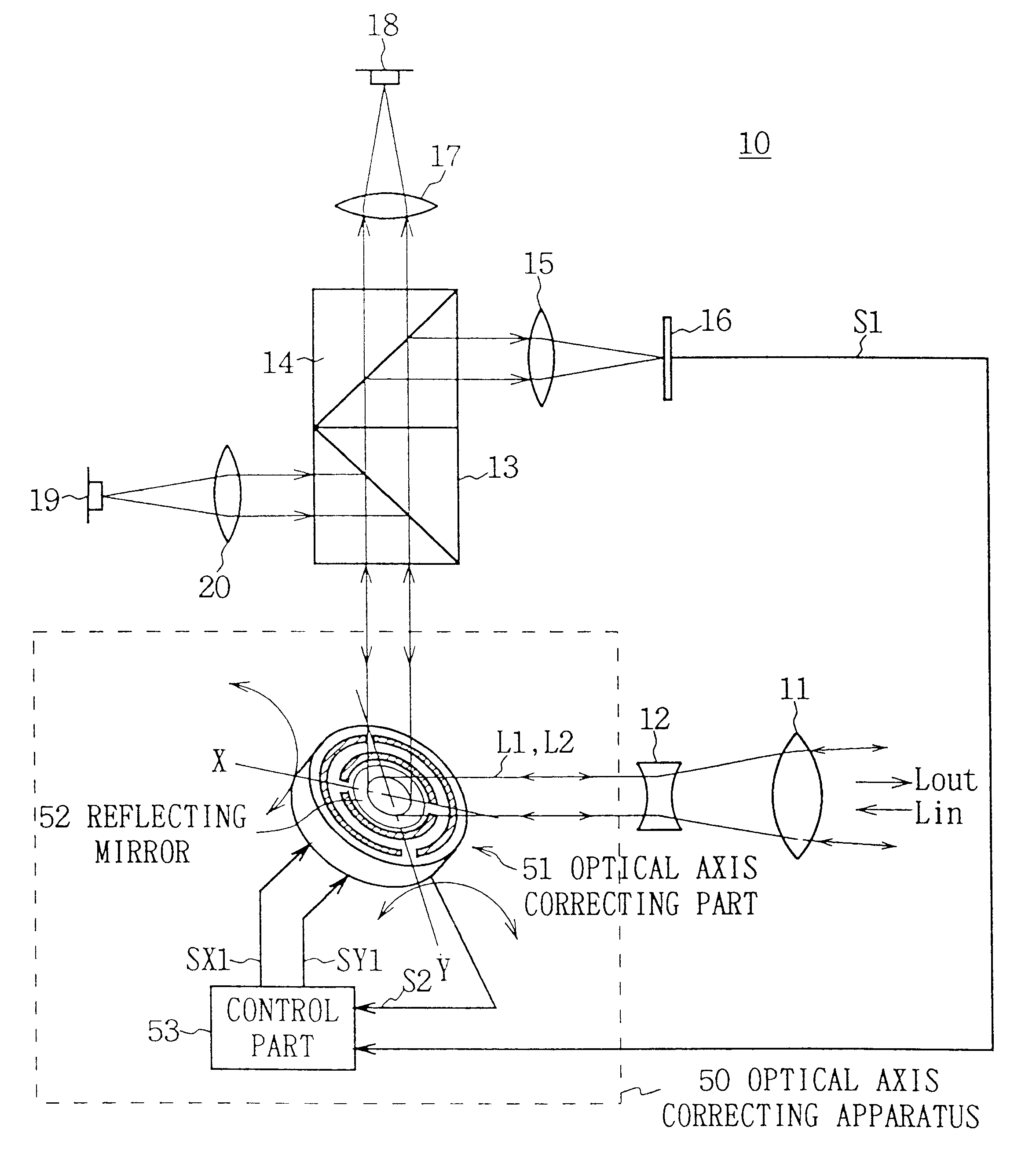
Referring to FIG. 4, numeral 10 generally shows an optical space transmission system providing an optical axis correcting apparatus 50 of the present invention. A laser beam which is modulated based on an information signal and is emitted from a semiconductor laser 19 in transmission, is converted into a parallel beam L2 through a lens 20, is reflected by a beam splitter 13. Then, the parallel beam L2 is reflected by the reflecting mirror 52 of an optical axis correcting part 51 in an optical axis correcting apparatus 50, and then is emitted as an emitted beam L.sub.out through a concave lens 12 and a convex lens 11.

In reception, the optical space transmission system 10 converts an incident beam L.sub.in from the optical space transmission system of a communicating party (not shown in FIG. 4) into a parallel beam L1 throu...


PUM


Abstract

An optical axis correcting apparatus for correcting the optical axes of light beams from a communicating party in an optical space transmission system that transmits and receives the light beams to / from the communicating party, comprises, in order to further accurately correct an optical axis with a simple configuration, optical axis changing means for changing the angle of a reflecting mirror placed in the optical path of the light beam and for changing the optical axis of the light beam to be reflected by the reflecting mirror, optical axis direction detecting means for detecting the direction of the optical axis of the light beam that is changed by the optical axis changing means, optical axis adjusting means for adjusting the angle of the reflecting mirror based on the direction of optical axis of the light beam detected by the optical axis direction detecting means through the optical axis changing means in order to adjust the direction of the optical axis of the light beam toward the communicating party, and correction means for detecting a change of angle occurred in the reflecting mirror owing an oscillation applied to the reflecting mirror and for correcting the angle of the reflecting mirror based on the detected result.

Description

1. Field of the InventionThis invention relates to an optical axis correcting apparatus and a method of correcting an optical axis, and more particularly, is suitably applied to an optical axis correcting apparatus of an optical space transmission system that spatially transmits light beams.2. Description of the Related ArtA transmission system transmits data from the transmitting side to the receiving side through a cable circuit or by radio. A construction to transmit data from transmitting side to receiving side through a cable circuit has ways in which the cable circuit is provided virtually and underground. However, both methods require troublesome procedure and large-scale construction. On the other hand, to transmit data from the transmitting side to the receiving side by radio, a prescribed frequency band must be allocated out of a limited electric wave source, and realizing it is difficult because practically there is limitation in the number of circuits.Then, in recent yea...

Claims


Application Information

Patent Timeline
Patent Type & Authority Patents(United States)
IPC IPC(8): G02B26/08G02B27/14G02B7/182H04B10/10G02B7/198G02B7/00H04B10/07H04B10/11
CPCG02B7/1821G02B26/0816G02B27/144G02B27/145H04B10/1125
Inventor IRIYAMA, TOSHIHISAITO, YUJIRO
Owner SONY CORP
Why Eureka
Try Eureka