Optical Space Transmitter and Optical Space Transmission Method for Wavelength-Multiplexed Light

a technology of optical space transmitter and wavelength-multiplexed light, which is applied in the field of optical space transmitter and optical space transmission method, for wavelength-multiplexed light, can solve the problem of large signal capacity, achieve high precision angle adjustment, enhance safety, and simple configuration

Inactive Publication Date: 2007-10-18
PANASONIC CORP
View PDF14 Cites 15 Cited by
  • Summary
  • Abstract
  • Description
  • Claims
  • Application Information

AI Technical Summary

Benefits of technology

[0044] According to the wavelength-multiplexing optical space transmitter, with a simple configuration using a single diffusion plate and without requiring a highly precise angle adjustment for optical axes, optical signals having wavelengths different from each other sent from a plurality of light sources can be multiplexed to obtain an optical signal whose optical axes therein are aligned, thereby generating a frequency-multiplexed signal light. Also, without providing a separate optical system for enhancing safety, a conversion to obtain a diffuse light having enhanced safety can be simultaneously performed.

Problems solved by technology

However, there is a gradual trend that a capacity of a signal becomes large and such a signal is to be transmitted with high speed, and thus, a high speed transmission and a large capacity are also required for an optical space transmission system.

Method used


Image

  • Optical Space Transmitter and Optical Space Transmission Method for Wavelength-Multiplexed Light
  • Optical Space Transmitter and Optical Space Transmission Method for Wavelength-Multiplexed Light
  • Optical Space Transmitter and Optical Space Transmission Method for Wavelength-Multiplexed Light

Examples


embodiment 1

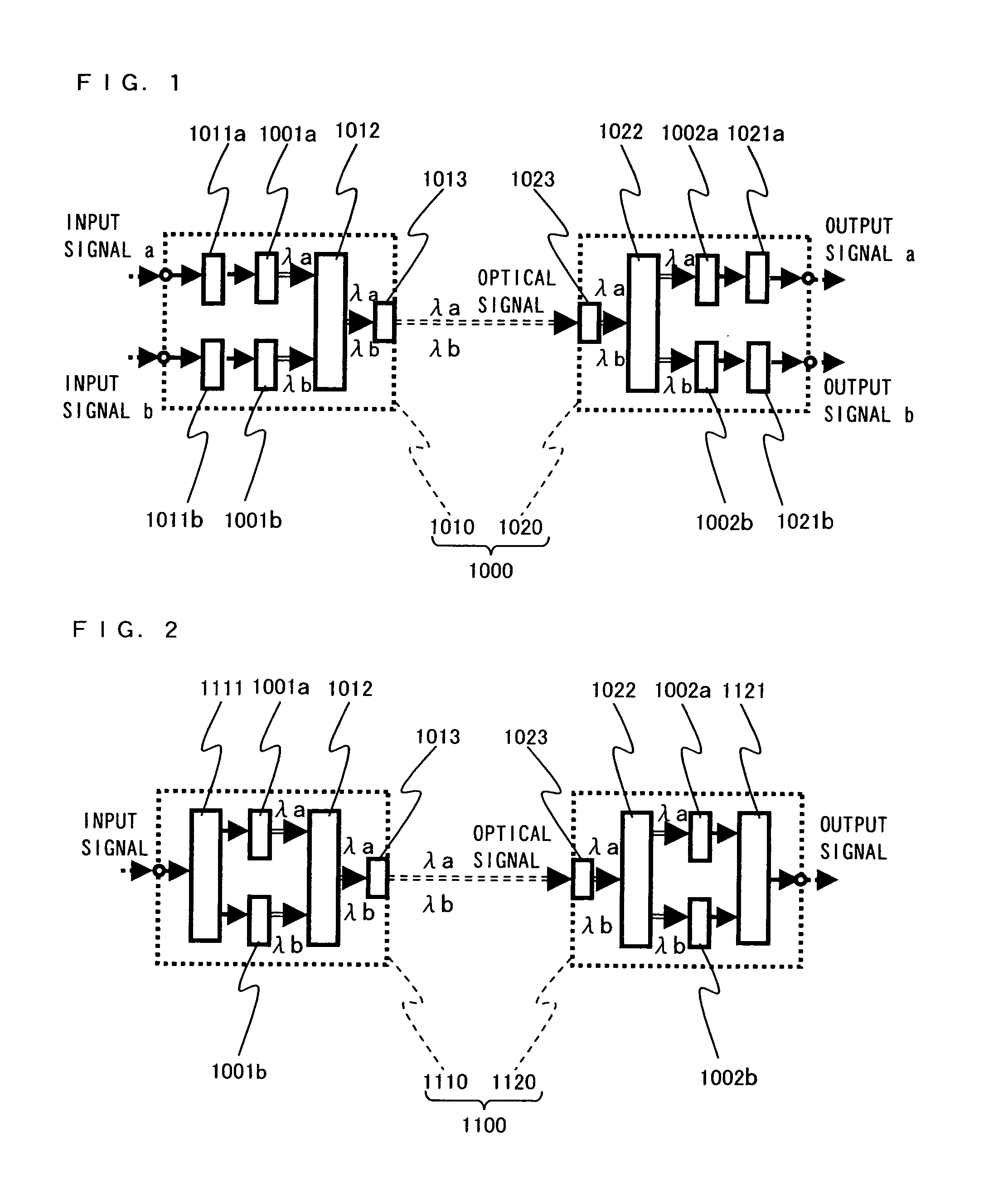
[0078]FIG. 1 is a block diagram showing a configuration of a wavelength multiplexing optical space transmission system using a wavelength multiplexing optical space transmitter of the present invention.

[0079] A wavelength multiplexing optical space transmission system 1000 includes an optical transmitter 1010 and an optical receiver 1020. The optical transmitter 1010 includes: modulation circuits 1011a and 101b; light sources 1001a and 1001b; an optical multiplexing section 1012; and a transmission optical system 1013, and the optical receiver 1020 includes: a reception optical system 1023; an optical demultiplexing section 1022; light receiving sections 1002a and 1002b; and demodulation circuits 1021a and 1021b. In FIG. 1, double line arrows and double dashed line arrows represent optical signals, and single line arrows and single dashed line arrows represent electrical signals.

[0080] Next, operations of the wavelength multiplexing optical space transmission system are described....

embodiment 2

[0094]FIG. 8 is a side view showing a configuration of a wavelength multiplexing optical space transmitter according to Embodiment 2 of the present invention.

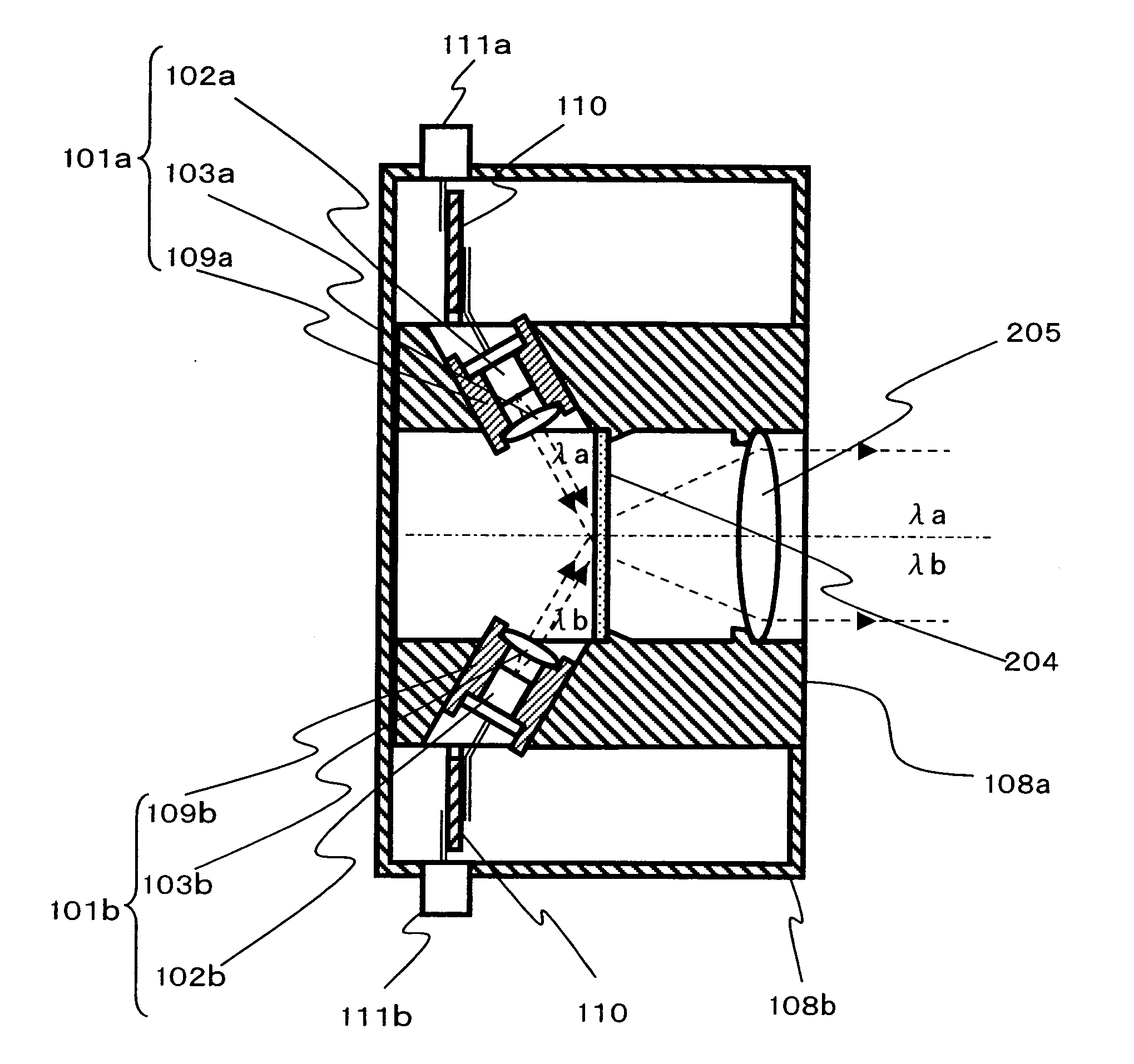
[0095] In FIG. 8, light sources 201a, 201b, and 201c respectively include light emitting elements 202a, 202b, and 202c, and light source lenses 203a, 203b, and 203c. The light emitting elements 202a, 202b, and 202c respectively output signal lights of wavelengths λa, λb, and λc different from each other. The light source lenses 203a, 203b, and 203c are arranged such that the axes thereof are approximately aligned with those of the corresponding light emitting elements 202a, 202b, and 202c. Optical signals outputted from the light emitting elements 202a, 202b, and 202c are converted, by the light source lenses 203a, 203b, and 203c, respectively, into substantially parallel lights, and the parallel lights irradiate a diffusion plate 104. The light emitting elements 102a and 102b modulate, by modulation circuits connected thereto...


PUM


Abstract

Provided is an optical space transmitter and an optical space transmission method, for wavelength-multiplexed light, capable of obtaining a wavelength-multiplexed signal by multiplexing optical signals having a plurality of wavelengths with a simple configuration and without requiring highly precise adjustment for optical axes and enhancing safety for a human body, including, e.g., the eyes. The transmitter has a configuration for which light sources (101a, 101b) for outputting signal lights having wavelengths different from each other are arranged so as to irradiate an approximately identical portion of a diffusion plate (104), a diffuse light outputted from the diffusion plate (104) is converted, by a radiation lens (105), into a light traveling with an angle suitable for transmission in a free space, and the converted light is passed out to the free space. Accordingly, without requiring a highly precise adjustment for optical axes, it is possible to realize a wavelength multiplexing optical space transmitter operable to multiplex optical signals having wavelengths different from each other based on a coincided optical axis, and to reduce risk of eye injury.

Description

TECHNICAL FIELD [0001] The present invention relates to an optical space transmitter and an optical space transmission method, for optical signals, for transmitting information data such as a video signal, an audio signal, and a digital data signal as an optical signal via a free space. More specifically, the present invention relates to an optical space transmitter and an optical space transmission method, for wavelength-multiplexed light, for multiplexing optical signals having a plurality of wavelengths and transmitting the multiplexed optical signal to an optical receiver via a free space. BACKGROUND ART [0002] An optical space transmission system for transmitting an optical signal between an optical transmitter and an optical receiver via a free space has been in practical use. However, there is a gradual trend that a capacity of a signal becomes large and such a signal is to be transmitted with high speed, and thus, a high speed transmission and a large capacity are also requi...

Claims


Application Information

Patent Timeline
Patent Type & Authority Applications(United States)
IPC IPC(8): H04B10/12H04B10/11H04B10/112H04J14/00H04J14/02
CPCH04B10/1121H04J14/02H04B10/506
Inventor IEDA, TOMOAKI
Owner PANASONIC CORP
Why Eureka
Try Eureka