Optical-transmission-space determining apparatus and optical-space transmission apparatus

a technology of optical space and determining apparatus, applied in the direction of instruments, optical elements, mountings, etc., can solve the problems of inability to respond to a quick variation, the foregoing known optical space transmission apparatus is incapable of tracking error of light beam and accordingly to an increase or decrease in received light optical power, and the limitation of the installation pla

Inactive Publication Date: 2005-12-01
CANON KK
View PDF9 Cites 13 Cited by
  • Summary
  • Abstract
  • Description
  • Claims
  • Application Information

AI Technical Summary

Benefits of technology

[0012] The present invention is directed to an optical-space transmission apparatus for use in communication by using light propagating in a space. In one aspect of the present invention, an optical-space transmission apparatus includes a light-receiving unit, an optical system including a movable mirror and introducing light incident thereon to the light receiving unit with the movable mirror, a controller controlling drive of the movable mirror, and a detecting unit detecting an intensity of the light received in the light-receiving unit. The controller modifies a control characteristic of the movable mirror in accordance with a change in the received-light intensity.

Problems solved by technology

As a result, irrespective of the fact that the light beam normally reaches the counterpart apparatus, the scintillation causes an emitting direction of the light beam to be vibrated, thereby leading to a tracking error of the light beam and accordingly to an increase or decrease in received-light optical power.
Unfortunately, even though many optical-space transmission apparatuses are installed on the roof top of a building, indoors or the like where the apparatuses undergo a relatively small level of vibration, some apparatuses are possibly installed at places, other than the above-mentioned ones, where the apparatuses are subjected to vibration or a pressure of window.
Because of limiting a response characteristic of the automatic-tracking function only in the low-frequency range, the foregoing known optical-space transmission apparatus is incapable of responding to a quick variation such as vibration, whereby its installation place is limited.
Hence, the limiting the function only in the low frequency range causes the transmission apparatus to be operated in a state in which an effect of the automatic tracking function is not fully achieved.

Method used


Image

  • Optical-transmission-space determining apparatus and optical-space transmission apparatus
  • Optical-transmission-space determining apparatus and optical-space transmission apparatus
  • Optical-transmission-space determining apparatus and optical-space transmission apparatus

Examples


first embodiment

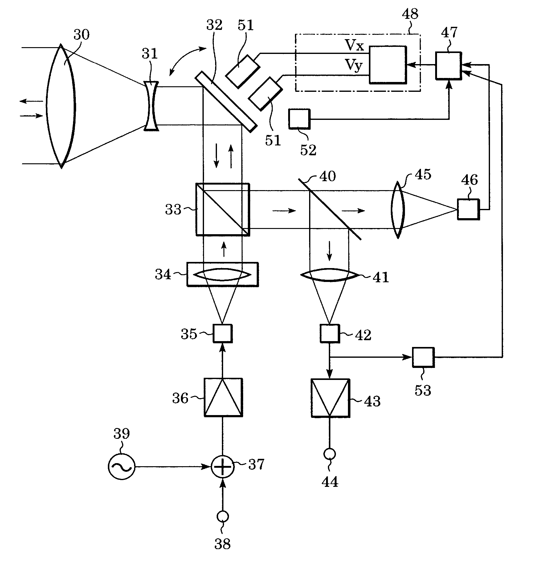
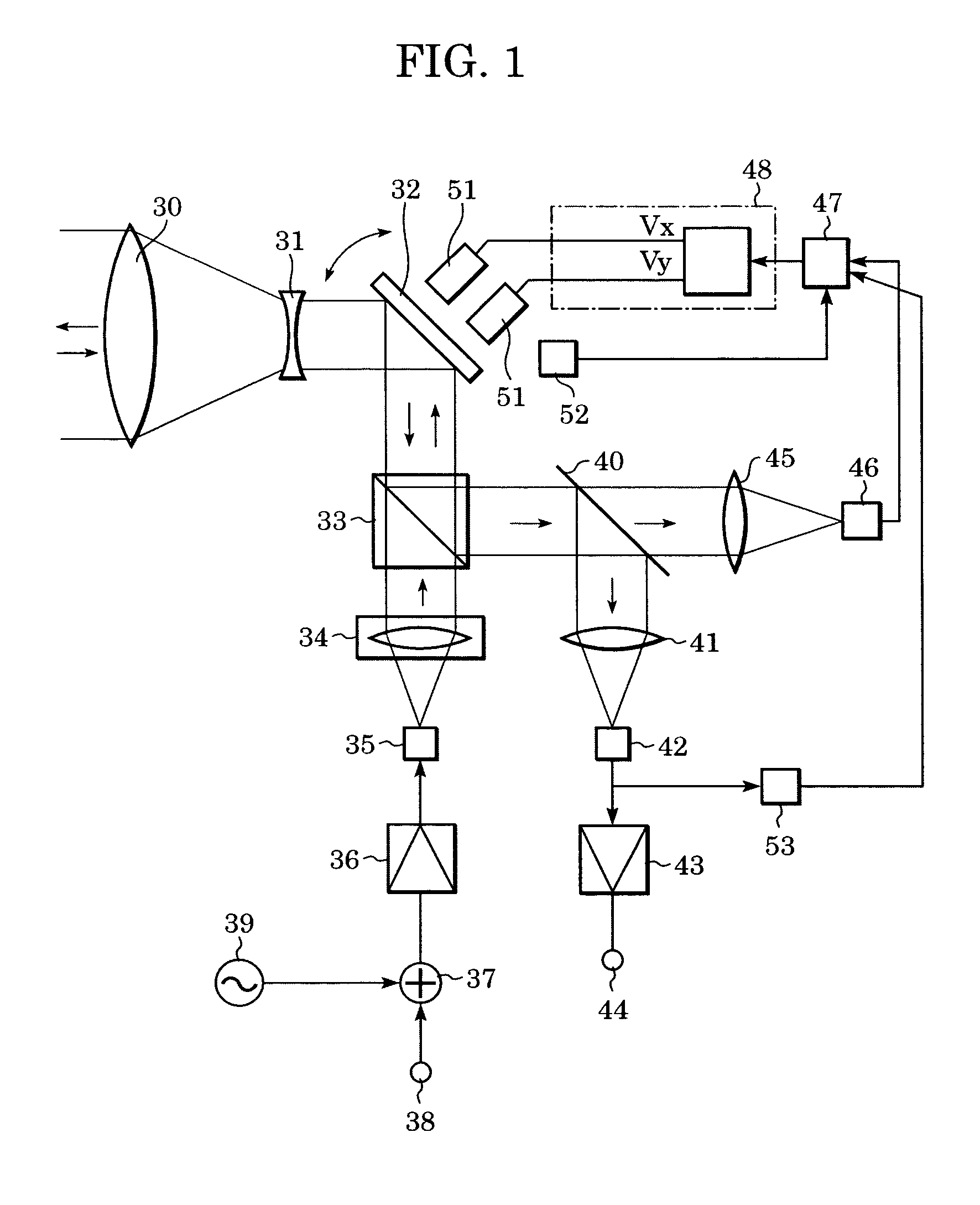
[0022] Referring now to FIG. 1, the structure of an optical-space transmission apparatus according to a first embodiment of the present invention will be described. FIG. 1 is a perspective view of the optical-space transmission apparatus according to the present embodiment.

[0023] A transmitting main signal from a signal input unit 38 is multiplexed with an automatic-tracking pilot signal from a pilot-signal generating circuit 39 by a optical multiplexing circuit 37; is changed to an optical signal by a light-emitting device 35 after passing through an amplifier 36; passes through a collimator lens 34 and a polarization beam splitter 33; is reflected from a movable mirror 32 (a first movable unit); and, as a transmitting light beam, is projected onto a counterpart apparatus (not shown) through lenses 31 and 30.

[0024] A received light beam from the counterpart apparatus passes through the lenses 30 and 31 and the movable mirror 32; is reflected from the polarization beam splitter 33...

second embodiment

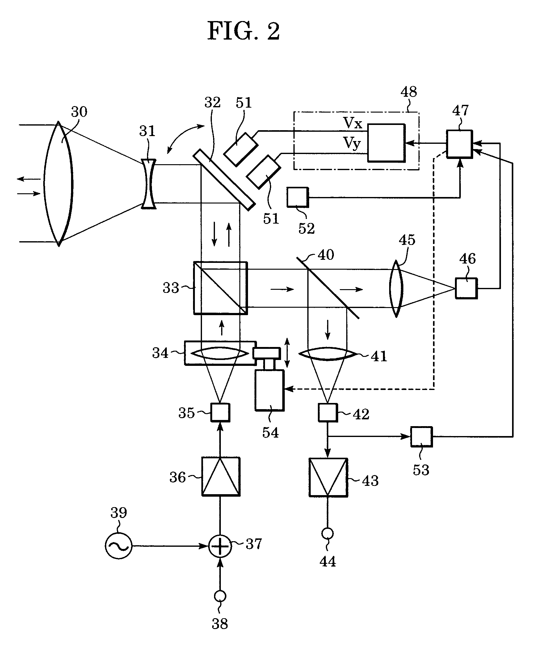
[0040]FIG. 2 is a perspective view of an optical-space transmission apparatus according to a second embodiment of the present invention. According to the present embodiment, on the basis of a difference (a level of scintillation) between two of, for example, the mean, the minimum, and the maximum values of a received-light intensity, the apparatus operates so as to increase a diverging angle of a transmitting light beam to an extent that scintillation does not cause a tracking error, while leaving the control speed unchanged. The same parts as those in the first embodiment are denoted by the same reference numbers and their descriptions are omitted.

[0041] In the same manner as in the first embodiment, when the operating circuit 47 determines that a level of scintillation exceeds a predetermined one and that there is hence a risk that a tracking error caused by the scintillation adversely affects signal transmission, for example, occurrence of a transmission error, the operating cir...


PUM


Abstract

An optical-space transmission apparatus for use in communication by using light propagating in a space includes a light-receiving unit, an optical system including a movable mirror and introducing light incident thereon to the light receiving unit with the movable mirror, a controller controlling drive of the movable mirror, and a detecting unit detecting an intensity of the light received in the light-receiving unit. The controller modifies a control characteristic of the movable mirror in accordance with a change in the received-light intensity.

Description

BACKGROUND OF THE INVENTION [0001] 1. Field of the Invention [0002] The present invention relates to an optical-transmission-space determining apparatus for determining a state of the atmosphere where a light beam propagates and an optical-space transmission apparatus for use in telecommunication by propagating a light beam. [0003] 2. Description of the Related Art [0004] An optical-space communication system for use in communication between a counterpart apparatus (remotely located) and an apparatus (locally located) by means of a light beam through the atmosphere as a transmission channel allows for a large capacity of data to be communicated at high speeds, is more portable than a wire communication system using, for example, an optical fiber, and also its communication channel can be easily and freely established. [0005] In order to establish a reliable communication channel with this optical-space communication system, a light beam emitted from the locally located apparatus mus...

Claims


Application Information

Patent Timeline
Patent Type & Authority Applications(United States)
IPC IPC(8): H04B10/11H04B10/07H04B10/114
CPCH04B10/1125
Inventor SAKANAKA, TETSUOOTSUBO, MASATOSHI
Owner CANON KK
Why Eureka
Try Eureka