Golf putter

Inactive Publication Date: 2001-01-23
WRIGHT VERNON V
View PDF13 Cites 71 Cited by
  • Summary
  • Abstract
  • Description
  • Claims
  • Application Information

AI Technical Summary

Problems solved by technology

The relatively simply stated principle of smoothly imparting a rolling motion to the ball for movement along its intended path or line, is actually very difficult to repeatedly and

Method used


Image

  • Golf putter
  • Golf putter
  • Golf putter

Examples


Embodiment Construction

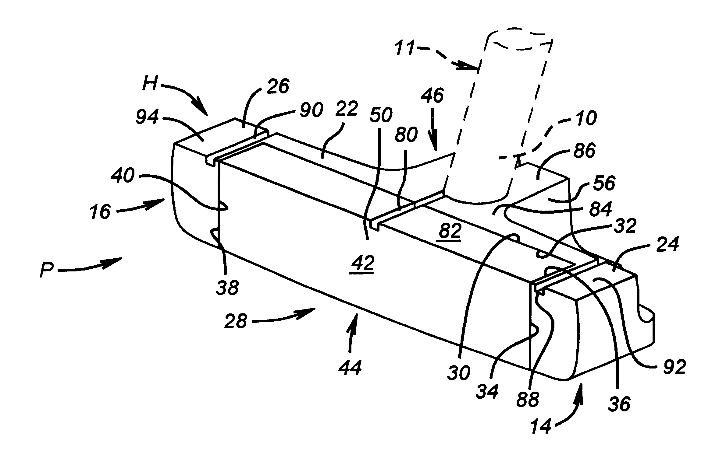
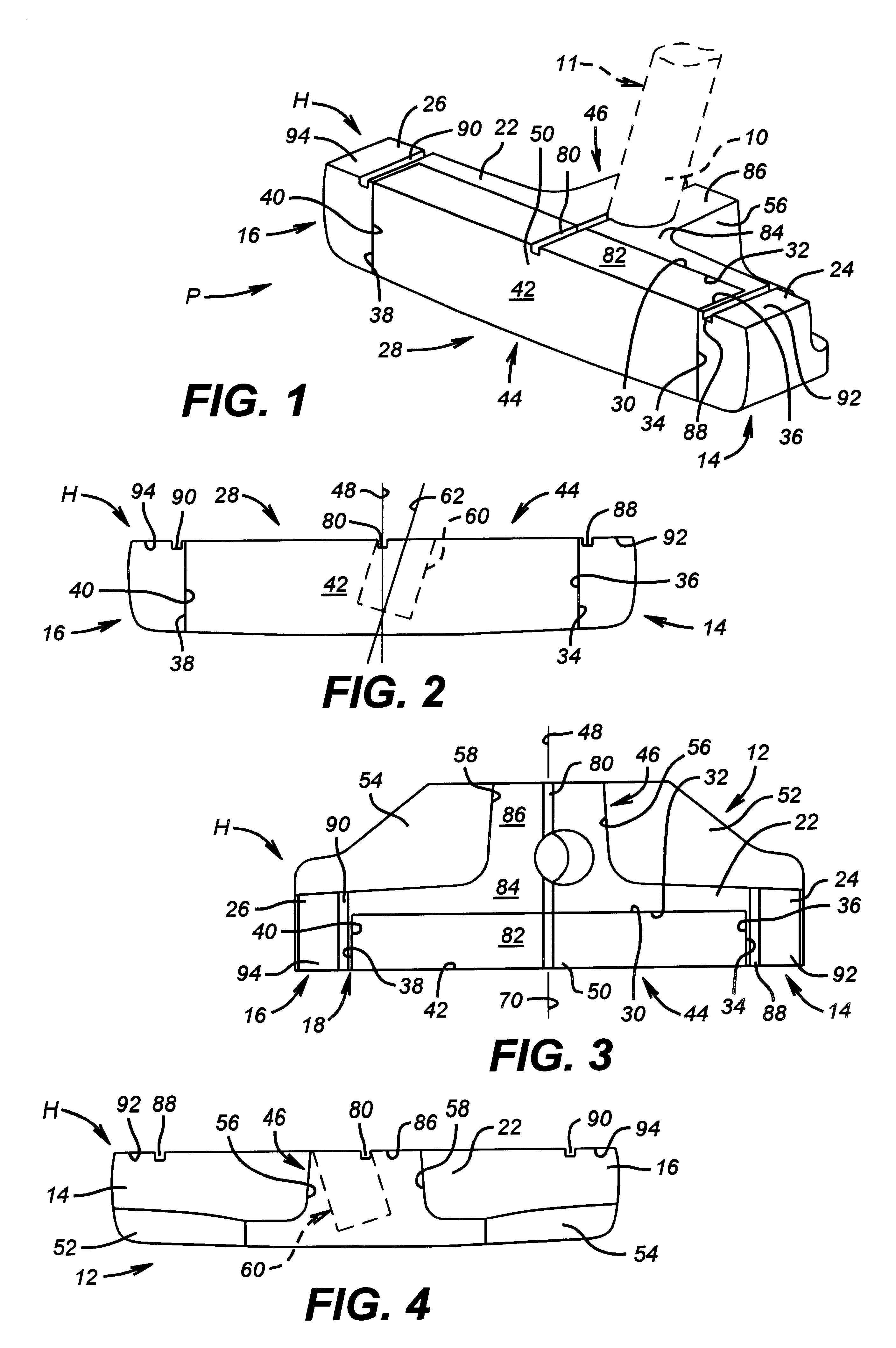
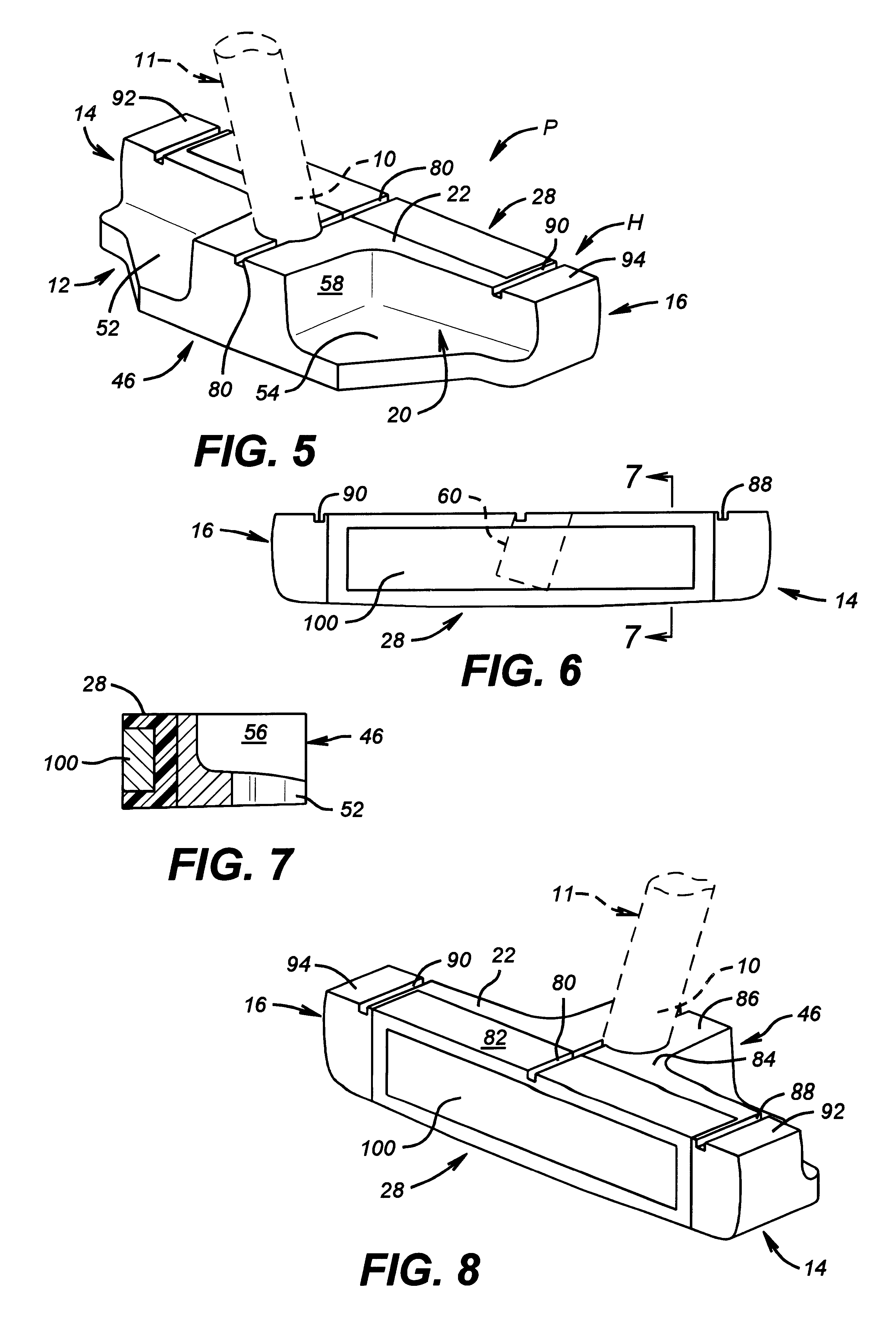
In the drawings, the letter P designates generally a new and improved putter according to the present invention. The putter P includes a club or putter head H mounted on a lower portion 10 of a club shaft 11. The club shaft 11 is conventional and may be of any suitable length in its upward extent from the lower portion 10 mounted with the club head H. The club shaft 11, as is conventional, has a club grip (not shown) mounted at its upper end. The club grip may be of any of numerous commercially available types.

The club head H is formed of a suitable metal alloy, such as a manganese alloy and includes a sole plate or face member 12. A heel portion 14 and a toe portion 16 are formed extending upwardly from the sole plate portion 12 of the club head H. The heel portion 14 and toe portion 16 are spaced laterally from each other by a gap 18 on a front portion 20 of the sole plate 12. The gap 18 is formed inwardly of a retainer plate 22 which extends upwardly from the sole plate 12. The r...


PUM


Abstract

A golf putter improves a golfer's ability to consistently impart a smooth putting stroke on the ball. The putter has an elastomer insert extending over a ball striking surface formed on the head of the club head. An inertial mass or ballast is formed at a rear central portion of the club head, with center portions of the ballast mass aligned with the vertical center line of the ball striking surface. The shaft portion of the putter is connected to the club head so that the longitudinal axis of the shaft intersects the center line of the club head and the inertial mass. The club head also has a base plate portion to assist the golfer in club grip and alignment during "set up" before the actual putting stroke.

Description

1. Field of the InventionThe present invention relates to golf clubs, more specifically to putters.2. Description of the Related ArtNo aspect of golf receives any more attention, analysis and study than putting. In a round of even par golf, two strokes per hole are allocated to putts. Golfers are continually working on ways to improve or enhance their scores by reducing the number of putts used. The relatively simply stated principle of smoothly imparting a rolling motion to the ball for movement along its intended path or line, is actually very difficult to repeatedly and consistently achieve. Part of this problem is that the structure of a number of putters is often not of a type that makes it easy for a golfer to accomplish this seemingly easy task. The number and variety of putters used is great; almost every golfer has a different type of particular preferred club design of choice for use as their putter. Even so, a golfer may experiment with a wide variety of putters and putti...

Claims


Application Information

Patent Timeline
IPC IPC(8): A63B53/04
CPCA63B53/0487A63B2053/0441A63B2053/0491A63B2053/0416A63B53/0416A63B53/0441A63B60/02
Inventor WRIGHT, VERNON V.
Owner WRIGHT VERNON V
Why Eureka
Try Eureka