
Method and apparatus for managing redundant computer-based systems for fault tolerant computing

a computer-based system and fault-tolerant technology, applied in the field of computing environments, can solve problems such as the existence of faults and errors in the system, the reduction of the overall design complexity of the system at hand, and the complexity of the system with significant flexibility

Inactive Publication Date: 2001-01-23
ALLIEDSIGNAL INC
View PDF27 Cites 64 Cited by
  • Summary
  • Abstract
  • Description
  • Claims
  • Application Information

AI Technical Summary

Benefits of technology

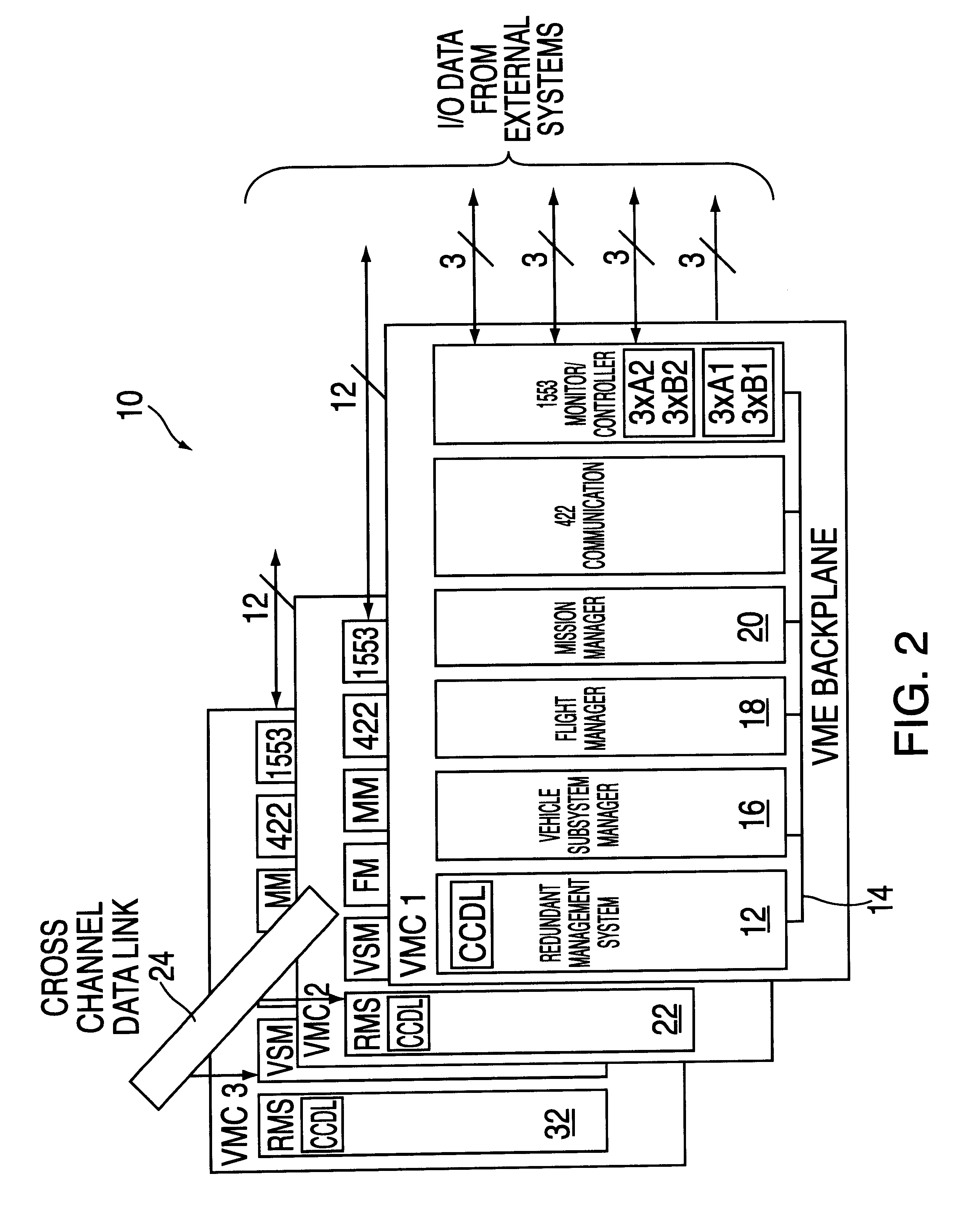
To implement the RMS, it is separated, physically or logically, from the application development. This reduces the overall design complexity of the system at hand. As such, the system developer can design applications independently and can rely on the RMS to provide redundancy management functions. The RMS and application integration is accomplished by a programmable bus interface protocol which connects the RMS to application processors.

Problems solved by technology

Fault tolerant computing assures correct computing results in the existence of faults and errors in a system.
The interweaving of the application with the redundancy management creates a more complex system with significantly decreased flexibility.
This reduces the overall design complexity of the system at hand.
Therefore, no single receiver failure can over drain current from other node's receivers resulting in a common mode failure across the system.
Nevertheless, immediate exclusion of transiently faulty components may decrease systems resources too quickly, and jeopardize mission success.
High penalty weights for certain faults will result in rapid exclusion of faulty channels when such faults occur.
In a two node configuration, the RMS cannot detect or exclude a faulty node.
As such, voting cannot be used to resolve conflicts.

Method used


Image

  • Method and apparatus for managing redundant computer-based systems for fault tolerant computing
  • Method and apparatus for managing redundant computer-based systems for fault tolerant computing
  • Method and apparatus for managing redundant computer-based systems for fault tolerant computing

Examples


Embodiment Construction

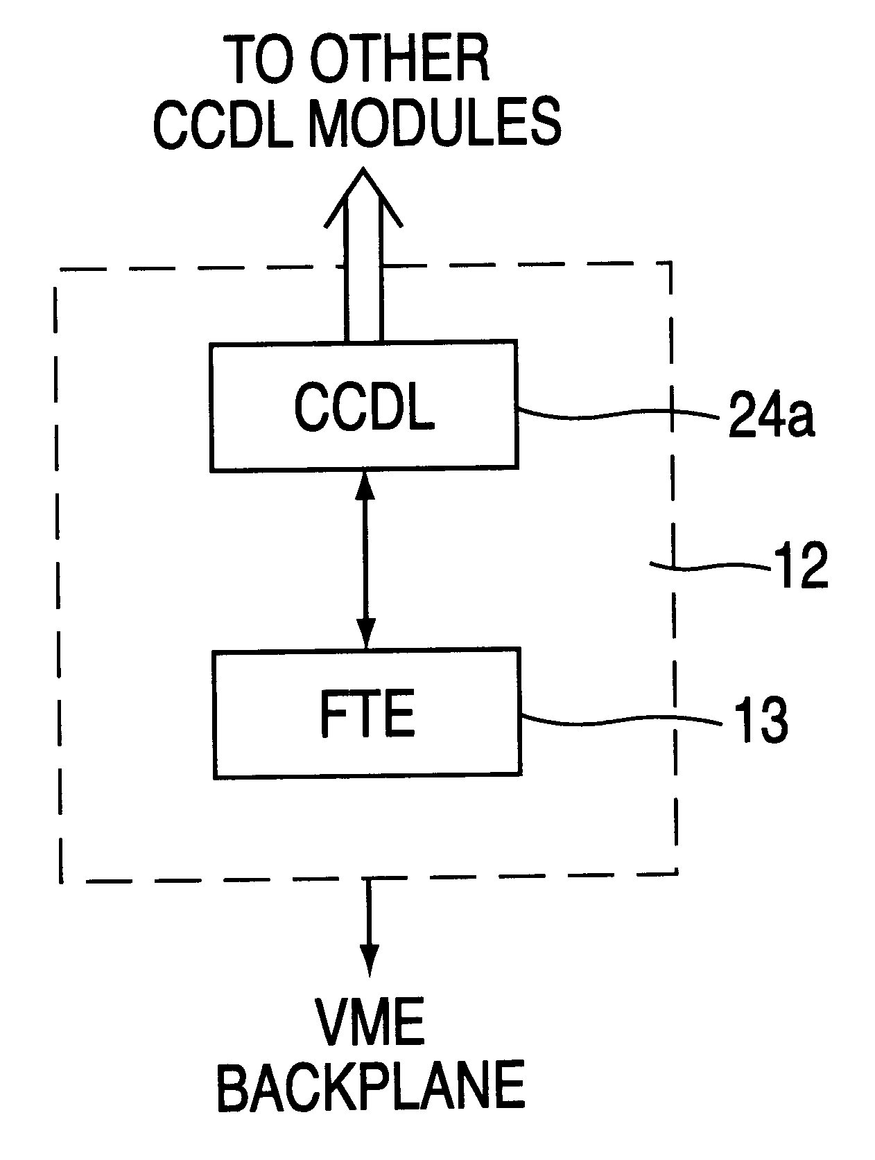
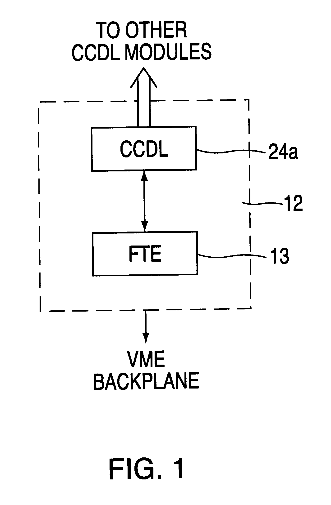
As previously mentioned, the RMS has two subsystems, Fault Tolerant Executive (FTE) and Cross-Channel Data Link (CCDL). The FTE consists of five modules (FIG. 5): 1) a Synchronizer 80; 2) a Voter 58; 3) a Fault Tolerator (FLT) 84; 4) a Task Communicator (TSC) 46; and 5) Kernal (KRL) 52. The functions of these modules will be described in the foregoing.

SYSTEM SYNCHRONIZATION

The Synchronizer (SYN) 80 (FIG. 5) establishes and maintains node synchronization for the system. It is required that, at any time, each individual RMS must be in, or operate in one of five states: 1)POWER_OFF; 2) START_UP; 3) COLD_START; 4) WARM_START; and 5) STEADY_STATE. FIG. 3 shows a state transistion diagram of an individual RMS and its five states.

POWER_OFF (PF) is the state when the RMS is non-operational and the power source of the associated computer is off for any reason. When the RMS is powered-up, the RMS unconditionally transitions to START-UP.

START_UP (SU) is the state after the computer has just be...


PUM


Abstract

A stand alone Redundancy Management System (RMS) provides a cost-effective solution for managing redundant computer-based systems in order to achieve ultra-high system reliability, safety, fault tolerance, and mission success rate. The RMS includes a Cross Channel Data Link (CCDL) module and a Fault Tolerant Executive (FE) module. The CCDL module provides data communication for all channels, while the FTE module performs system functions such as synchronization, data voting, fault and error detection, isolation and recovery. System fault tolerance is achieved by detecting and masking erroneous data through data voting, and system integrity is ensured by a dynamically reconfigurable architecture that is capable of excluding faulty nodes from the system and re-admitting healthy nodes back into the system.

Description

1. Field of the InventionThe present invention relates to computing environments, more particularly, it relates to a method for managing redundant computer-based systems for fault-tolerant computing.2. Background of the InventionFault tolerant computing assures correct computing results in the existence of faults and errors in a system. The use of redundancy is the primary method for fault tolerance. There are many different ways of managing redundancy in hardware, software, information and time. Due to various algorithms and implementation approaches, most current systems use proprietary design for redundancy management, and these designs are usually interwoven with application software and hardware. The interweaving of the application with the redundancy management creates a more complex system with significantly decreased flexibility.It is therefore an object of the present invention to provide a method for managing a redundant computer-based systems that is not interwoven with t...

Claims


Application Information

Patent Timeline
Patent Type & Authority Patents(United States)
IPC IPC(8): G06F11/00G06F11/18G06F9/52G06F15/177
CPCG06F11/181G06F11/182G06F11/188
Inventor ZHOU, JEFFREY XIAOFENGRODEN, III, THOMAS GILBERTBOLDUC, LOUIS P.PENG, DAR-TZENERNST, JAMES W.YOUNIS, MOHAMED
Owner ALLIEDSIGNAL INC
Learn More