
Hemming machine

a hemming machine and nut technology, applied in forging presses, manufacturing tools, forging/hammering/pressing machines, etc., can solve the problems of inability to achieve absolute synchronization between the rotatable shafts in every situation, inevitable leakage of hydraulic fluid, mess created, etc., and achieve the effect of limited swiveling movement of the nu

Inactive Publication Date: 2001-02-06
VALIANT CO LTD
View PDF3 Cites 30 Cited by
  • Summary
  • Abstract
  • Description
  • Claims
  • Application Information

AI Technical Summary

Benefits of technology

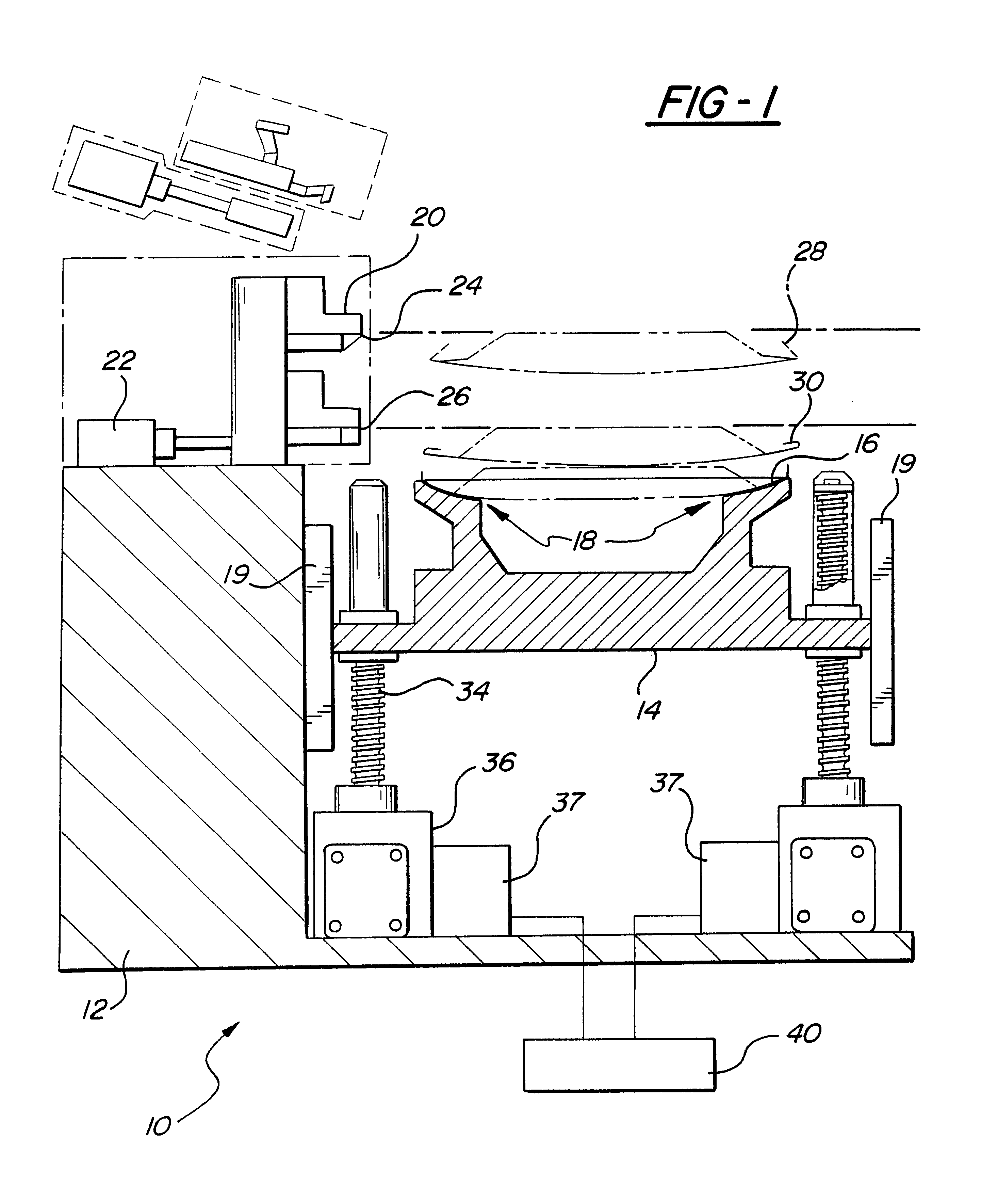
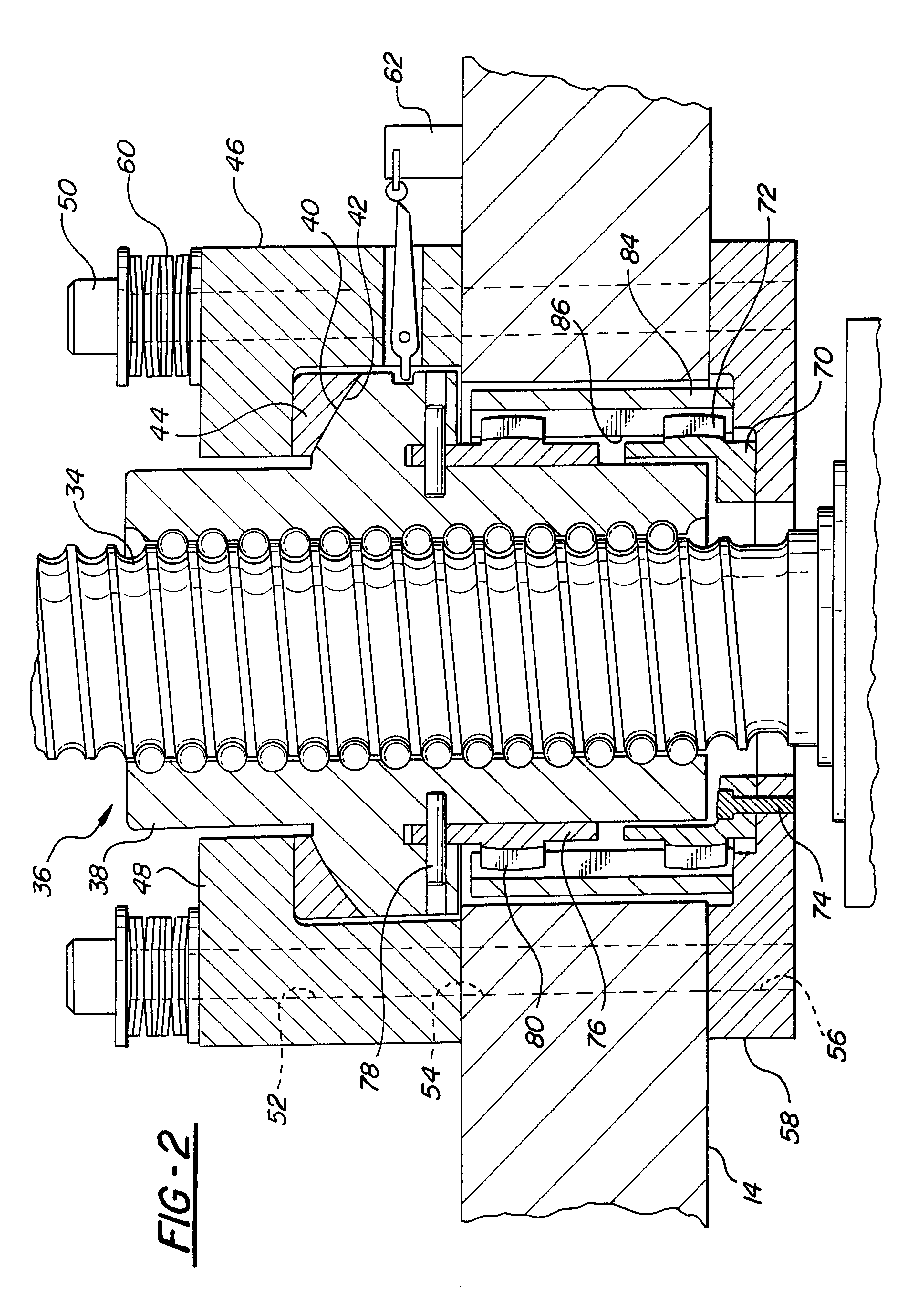
A second externally splined annulus is then coaxially disposed around and secured to the nut so that the second annulus is axially spaced from and coaxial with the first annulus. An internally splined tube is then disposed around the first and second annuli so that the internal splines on the tube intermesh with the external splines on the annuli. Consequently, the annuli, together with the internally splined tube, preclude rotation of the nut relative to the nest so that rotation of the shaft axially displaces the nut together with the nest.
In order to permit angular or slight radial displacement of the shafts relative to each other as would occur unless the shafts are absolutely synchronized for rotation to each other, the nut is swivelly mounted to the nest. In the preferred embodiment of the invention, this swivel mounting means comprises a thrust bushing having a semispherical surface and a bushing retainer which secures the bushing against pure vertical movement to the nest. A complementary semispherical surface formed on the nut abuts against the semispherical surface on the bushing to thereby permit limited swiveling movement of the nut relative to the nest. Such limited swivel capability of the nut relative to the nest is sufficient to compensate for limited non-synchronism of the rotation of the threaded shafts, and let the servo-motor controller react against any incidental situation.

Problems solved by technology

The vertical movement provided by the cylinders is often erratic which slows down the operation of the hemming process and otherwise causes inaccuracies.
A major disadvantage of the previously known use of hydraulic cylinders for hemming machines is the inevitable leakage of the hydraulic fluid and the resulting mess created by such leakage.
In practice, however, such absolute synchronization between the rotatable shafts cannot be achieved in every situation, and does not allow a perfect balancing of the hemming effort applied on each edge of the part, in both pre-hemming and hemming positions.
Furthermore, any lack of synchronization between the electric motor actuated shafts may result in seizure and even destruction of the hemming machine.

Method used


Image

  • Hemming machine
  • Hemming machine
  • Hemming machine

Examples


Embodiment Construction

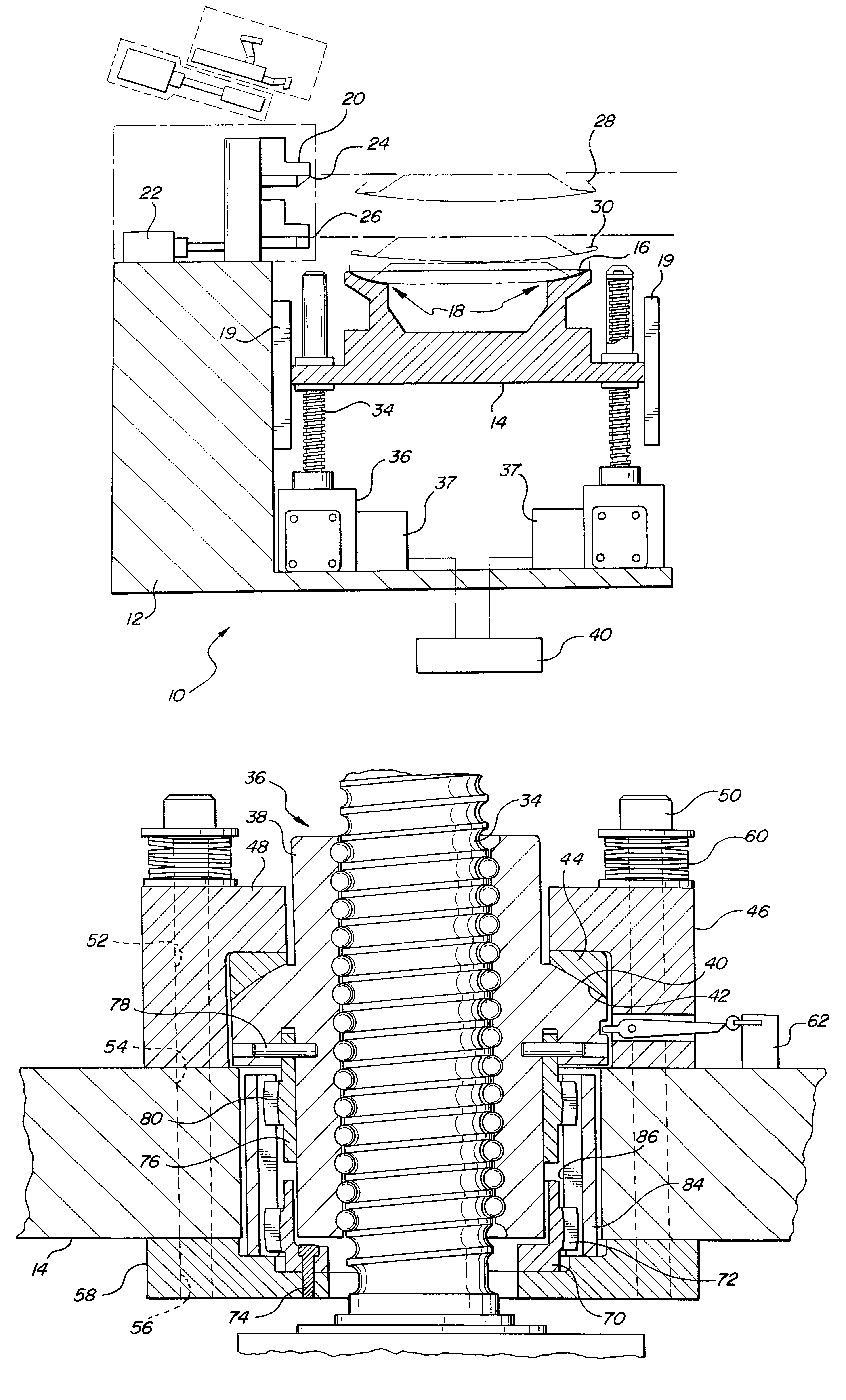
With reference first to FIG. 1, a diagrammatic view of a preferred embodiment of the hemming machine 10 of the present invention is there shown. The hemming machine 10 includes a base 12 and a nest 14. The nest 14 is adapted to receive and support a sheet metal part 16 to be hemmed at its peripheral surface 18. The hemming machine 10, in the conventional fashion, includes at least one and preferably four dies 20 which are laterally movable by an actuator 22 between a retracted position, illustrated in solid line in FIG. 1, and an extended position, illustrated in phantom line in FIG. 1. In its extended position, the die 20 registers with the part to be hemmed while, conversely, in its retracted position, the die 20 is moved laterally out of registry with the nest 14 in order to permit the finished hemmed part 16 to be removed from the nest 14 as well as a new sheet metal part 16 to be hemmed to be positioned on the nest surface 18.

Conventionally, the die set 20 includes two dies 24 ...


PUM

PropertyMeasurementUnit
Forceaaaaaaaaaa
Tensionaaaaaaaaaa
Displacementaaaaaaaaaa

Abstract

A hemming machine of the type having a base, a nest for supporting a sheet metal part to be hemmed, and at least one die is disclosed in which the nest supporting the part to be hemmed is vertically displaced against the dies in order to form the hem. The improvement includes at least three elongated and external shafts wherein each shaft has one end rotatably mounted to the base so that the shafts are spaced apart and parallel with each other. A nut threadably engages each shaft, and these nuts are swivelly secured to the nest which permits a small amount of angular and radial deflection of the nut and shafts during movement of the nest from its lower to its upper position. An electric servo-motor is associated with each threaded shaft to rotatably drive the shafts substantially in unison with each other during the travel approach phase, and then allows in final a slight disynchronization of them, to insure an equalization of the hemming effort applied on each edge of the part, in both pre-hemming and hemming operations.

Description

I. Field of the InventionThe present invention relates to hemming machines and, more particularly, to a sheet metal hemming machine utilizing a vertically movable nest supporting the sheet metal part to be hemmed to press against stationary dies which are moved into and out of an operating position.II. Description of the Prior ArtTypically sheet metal hemming devices utilize hydraulic cylinders for imparting vertical movement to the impacting punch or nest. The vertical movement provided by the cylinders is often erratic which slows down the operation of the hemming process and otherwise causes inaccuracies. This is particularly critical where multiple actuating hydraulic cylinders are employed, even if in final, this compliance allows a perfect balancing of the hemming effort on each edge of the part.A major disadvantage of the previously known use of hydraulic cylinders for hemming machines is the inevitable leakage of the hydraulic fluid and the resulting mess created by such lea...

Claims


Application Information

Patent Timeline
IPC IPC(8): B21D39/02
CPCB21D39/021Y10T29/53791Y10T83/8847
Inventor RAFFIN, LOUISBAULIER, DOMINIQUE R. M.
Owner VALIANT CO LTD
Learn More