Method and system for dynamically assigning addresses to an input/output device

Inactive Publication Date: 2001-02-06
IBM CORP
View PDF32 Cites 65 Cited by
  • Summary
  • Abstract
  • Description
  • Claims
  • Application Information

AI Technical Summary

Problems solved by technology

In the prior art, execution of a channel program for a single host system along multiple paths would likely create device-busy conditions detectable by the channel subsystem and cause unpredictable results.
Thus, with prior art servers

Method used


Image

  • Method and system for dynamically assigning addresses to an input/output device
  • Method and system for dynamically assigning addresses to an input/output device
  • Method and system for dynamically assigning addresses to an input/output device

Examples


Embodiment Construction

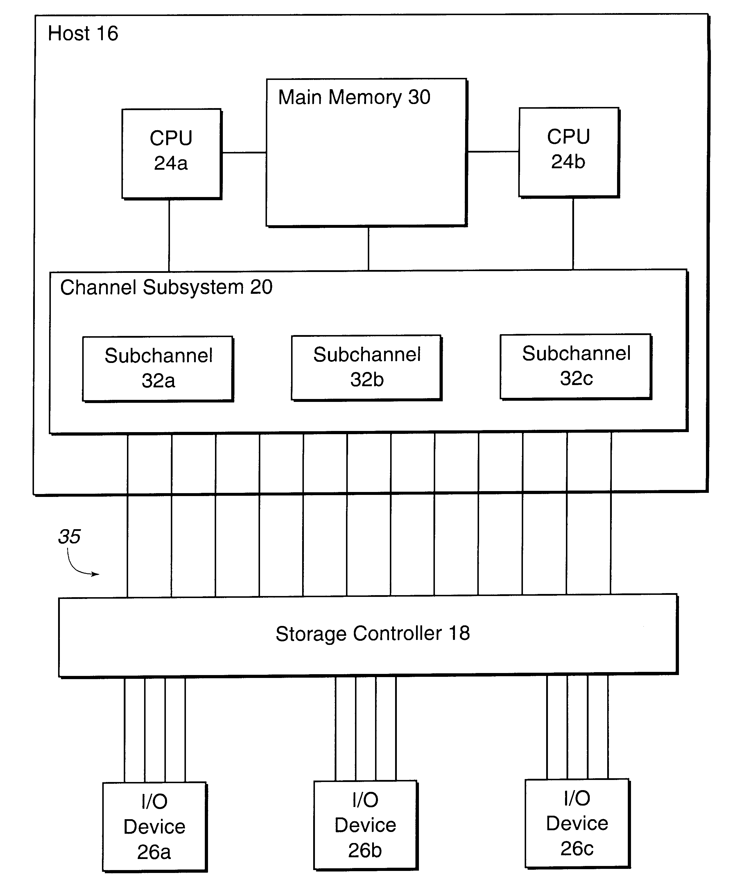
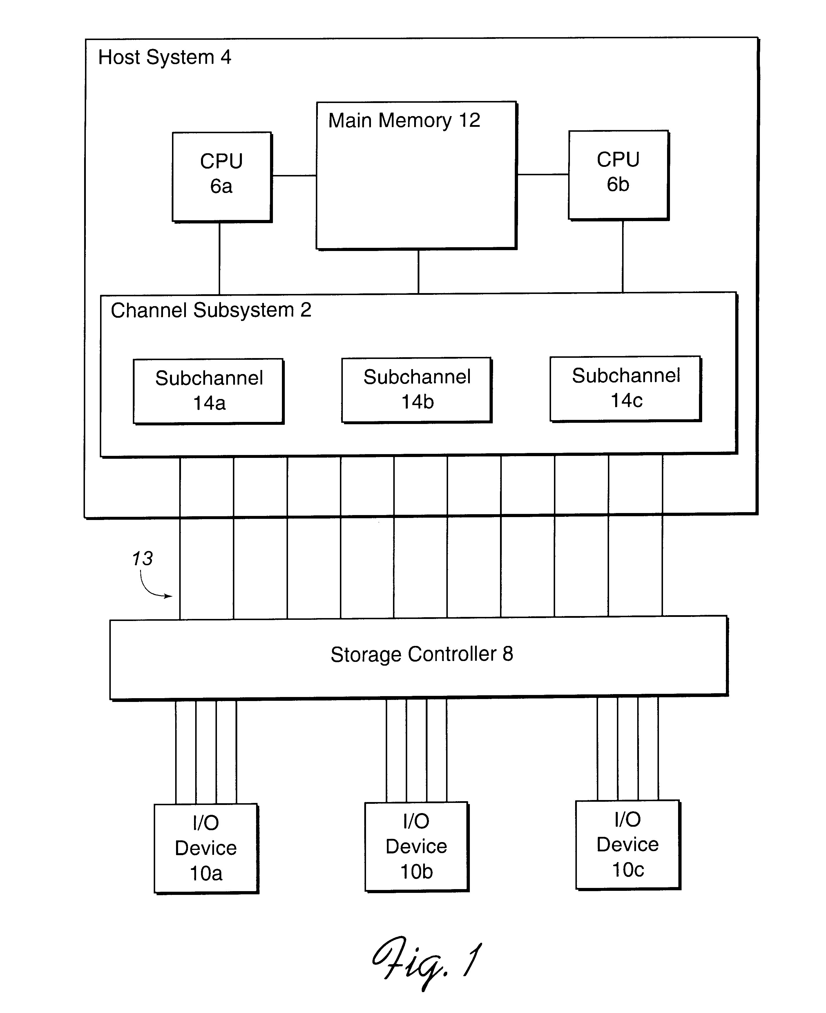
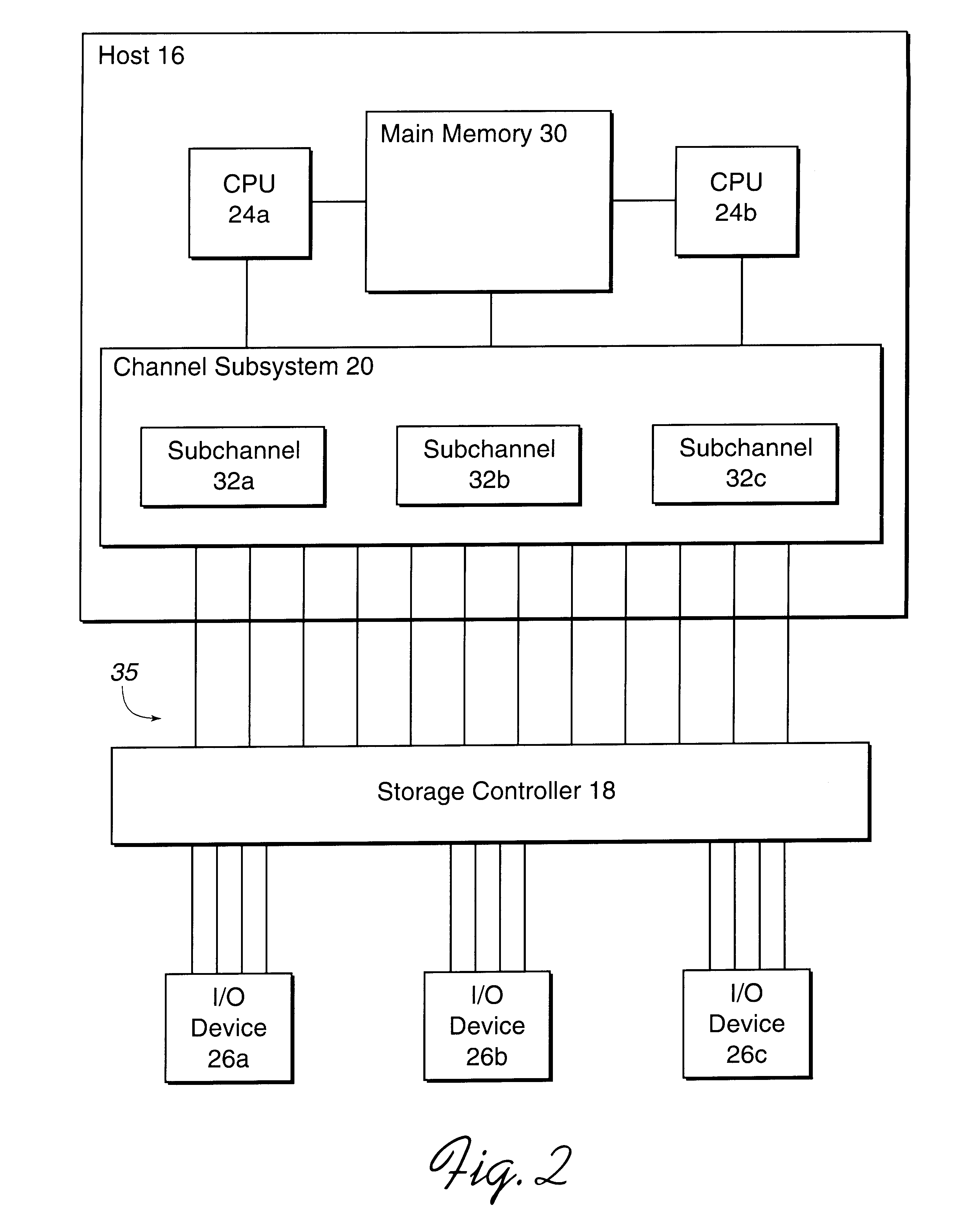
To overcome the limitations in the prior art described above, the present invention discloses a system for addressing an input / output (I / O) device. A first processing unit queries a second processing unit for information on base and associated alias addresses for at least one I / O device. The first processing unit processes the queried information to generate at least one base control block indicating a base address and a plurality of alias control blocks indicating a plurality of alias addresses. Each control block is associated with an address for addressing an I / O device. The first processing unit processes at least one alias control block associated with the I / O device and determines a base control block associated with the I / O device with which the alias control blocks are associated. The first processing unit then binds at least one alias control block to the determined base control block. The bound base and alias control blocks provide different addresses to address the same I...


PUM


Abstract

Disclosed is a system for dynamically assigning alias addresses to base addresses referencing an I/O device, such as a direct access storage device (DASD). In the system, at least one base control block indicates a base address and a plurality of alias control blocks indicate a plurality of alias addresses. Each control block is associated with an address for addressing an I/O device. A processing unit, such as a host computer system, processes at least one alias control block associated with the I/O device and determines a base control block associated with the I/O device with which the alias control blocks are associated. The processing unit then binds at least one alias control block to the determined base control block. The bound base and alias control blocks provide different addresses to address the same I/O device. Further, the bound base and alias addresses address the same I/O device for subsequent I/O operations until the processing unit detects a reassignment of the association of base and alias addresses.

Description

1. Field of the InventionThe present invention relates to a method and system for assigning alias to base addresses to provide multiple addresses to allow concurrent, multiple I / O operations directed toward the same I / O device.2. Description of the Related ArtFIG. 1 illustrates a hardware environment of a channel subsystem 2 included in a host system 4 providing communication between CPUs 6a, b and I / O devices 10a, b, c. A storage controller 8 controls access to the I / O devices 10a, b, c. The host system 4 communicates with the storage controller 8 via the channel subsystem 2 and subchannels 14a, b, c therein. The host system 4 includes CPUs 6a, b that contain the sequencing and processing facilities for instruction execution, interruption action, timing functions, initial program loading, and other machine-related functions. The CPUs 6a, b may be host systems. The I / O devices 10a, b, c may be comprised of printers, magnetic-tape units, direct-access-storage devices (DASDs), display...

Claims


Application Information

Patent Timeline
IPC IPC(8): G06F13/38
CPCG06F13/387
Inventor BEARDSLEY, BRENT CAMERONMERITT, ALLAN SAMUELPAULSEN, MICHAEL ALOYSIUSYUDENFRIEND, HARRY MORRIS
Owner IBM CORP
Why Eureka
Try Eureka