
Method of calibrating a multistage selective amplifier

a selective amplifier and multi-stage technology, applied in the direction of continuous tuning, multi-resonant circuit tuned to different frequencies, television systems, etc., can solve the problems of high memory space requirement, difficulty and disadvantages of prior art methods of achieving such calibrating and tuning of multi-stage selective amplifiers,

Inactive Publication Date: 2001-02-13
AG BECKER & CO +2
View PDF8 Cites 9 Cited by
  • Summary
  • Abstract
  • Description
  • Claims
  • Application Information

AI Technical Summary

Benefits of technology

The invention achieves several advantages. Most importantly, according to the invention, it is not necessary that large quantities of data are first stored in a memory and then called up in order to achieve the desired aligned operation. As a result of this, the tuning speed is increased without requiring increased memory capacity and without requiring additional circuit arrangements that take up additional space. The values determined according to the inventive method are always exact and nearly independent of any device tolerances.

Problems solved by technology

The prior art methods of achieving such calibrating and tuning of a multistage selective amplifier have suffered various difficulties and disadvantages.
However, in this known arrangement, it is disadvantageous that the characteristic curve function is already stored in the memory at the time of manufacturing the circuit, because any possible changes or differences that might arise over time cannot be taken into account.
As a further disadvantage, it must be considered that this known method necessarily involves a highly active data transfer traffic when changing frequencies.
One major disadvantage of the above described known method is the high memory space requirement, and a second major disadvantage is the data traffic that is necessary for each change of frequency or channel.
The necessity of carrying out such a data transfer substantially disadvantages a rapid searching or seeking function or a frequency jump function for tuning to a new frequency.
The use of such tuning and trimming potentiometers is considered to be inexact and subject to operating errors or deviations, and does not achieve rapid and exact tuning to a selected frequency.

Method used


Image

  • Method of calibrating a multistage selective amplifier
  • Method of calibrating a multistage selective amplifier
  • Method of calibrating a multistage selective amplifier

Examples


Embodiment Construction

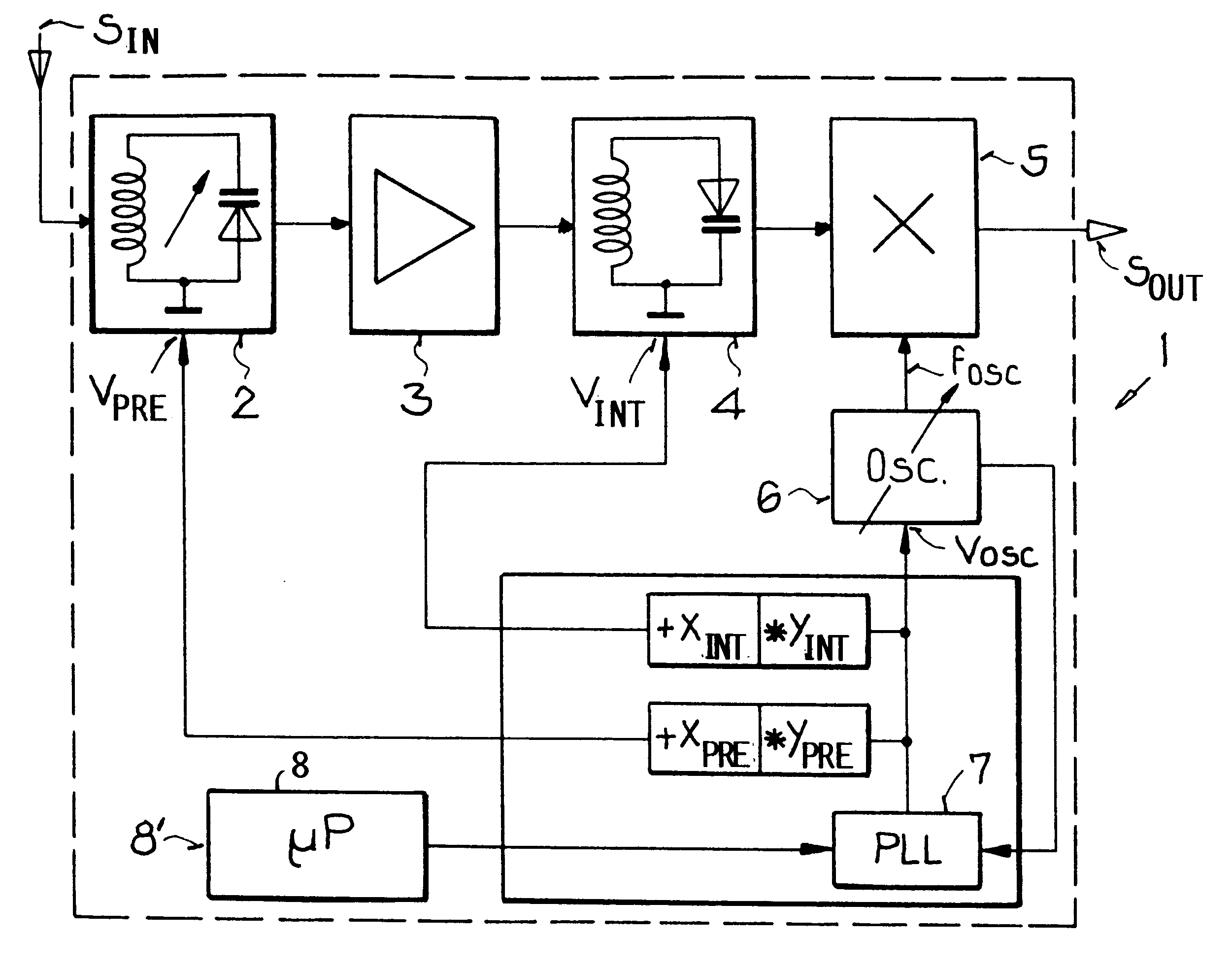
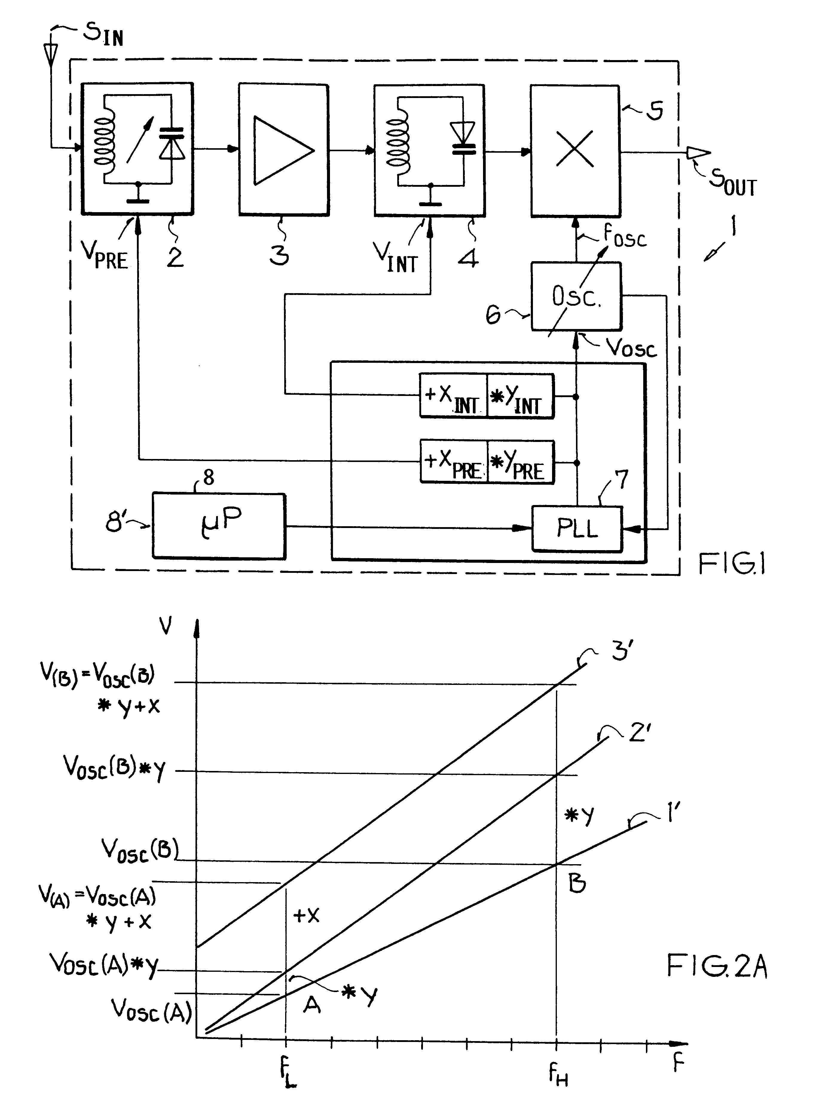
FIG. 1 schematically shows a block circuit diagram of a tuning circuit 1 according to the invention, i.e. a tuning circuit 1 for carrying out the method according to the invention. In this example embodiment, the input signals S.sub.I, such as TV or radio broadcast signals, are first filtered according to the respective selected receiving frequency in the pre-circuit or input circuit 2 and are then passed on to an amplifier 3, where the filtered signals are correspondingly amplified. Next, the filtered and amplified signals are provided to an intermediate circuit 4, which again filters the signals based on the receiving frequency or frequency range. The remaining signals at the output of the intermediate circuit 4 are provided into a mixer 5, which also receives an oscillator frequency signal F.sub.OSC from an oscillator circuit 6. The mixer 5 then filters out the remaining signals provided from the intermediate circuit 4 exactly to a prescribed third frequency dependent on or provi...


PUM


Abstract

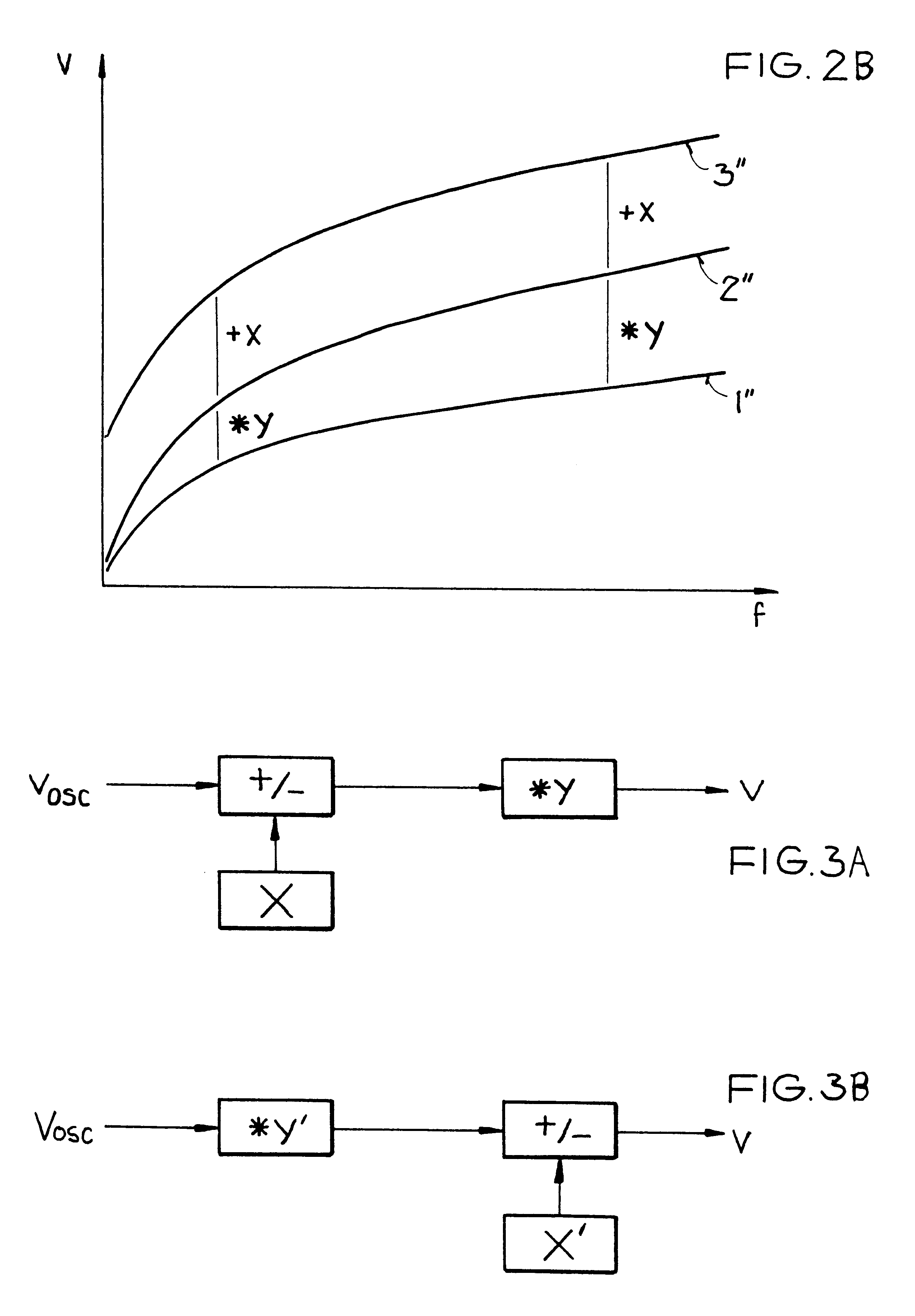
In a method for calibrating or aligning a multistage selective amplifier including an oscillator circuit and at least one tuning circuit, the tuning voltages respectively necessary for aligning the respective tuning circuits to the required receiving frequency are calculated directly from a mathematical relationship between the respective tuning voltage and the oscillator voltage. In order to achieve this, a characteristic multiplicative coefficient and a characteristic additive factor for each tuning circuit are stored in a memory upon manufacturing or switching on the device. In order to select a desired receiving frequency, the respective stored values as well as an oscillator voltage are provided to an amplification circuit, which correspondingly amplifies the oscillator voltage by the multiplicative coefficient and the additive factor and then provides the resulting output value as a tuning voltage to the respective tuning circuit. Thus, all necessary tuning voltages can be determined from the two respective stored values per tuning circuit, as necessary for selecting any desired receiving frequency.

Description

PRIORITY CLAIMThis application is based on and claims the priority under 35 U.S.C. .sctn.119 of German patent application 197 41 325.0, filed on Sep. 19, 1997, the entire disclosure of which is incorporated herein by reference.The invention relates to a method of calibrating or aligning a multistage selective amplifier, and particularly a tuner, that includes an oscillator circuit and at least one tuning circuit, wherein the receiving frequency is selected by providing an adjustable frequency-determining oscillator tuning voltage for the oscillator and adjustable frequency-determining tuning voltages for the respective tuning circuits.BACKGROUND INFORMATIONBy using selective amplifier circuits embodied as tuners, various broadcast programs, such as radio or television programs, or any signal in general can be received on a selected one of various frequencies, amplified and then reproduced. Tuning circuits are necessary for selecting the desired receiving frequency, which makes it po...

Claims


Application Information

Patent Timeline
IPC IPC(8): H03J1/00H03J3/28H03J3/32H03J3/00H03J3/24H04N5/50H04B1/26
CPCH03J1/0033H03J3/28H03J3/32
Inventor BECKER, KARL ANTONBRINKHAUS, STEFANGANZ, ARMINMEMMLER, BERNDKROEBEL, HANS-EBERHARDT
Owner AG BECKER & CO
Learn More