Dredging method and dredging apparatus

a technology of dredging apparatus and dredging method, which is applied in the direction of waterborne vessels, construction, vessel salvaging, etc., can solve the problems of reducing the operability and effectiveness of dams

Inactive Publication Date: 2001-02-20
MOBURON DESIGN OFFICE
View PDF9 Cites 27 Cited by
  • Summary
  • Abstract
  • Description
  • Claims
  • Application Information

AI Technical Summary

Problems solved by technology

Recently, 80% or more of the capacities of some dams are filled with sand and gravels, thereby reducing dam operability and effectiveness.

Method used


Image

  • Dredging method and dredging apparatus
  • Dredging method and dredging apparatus
  • Dredging method and dredging apparatus

Examples


first embodiment

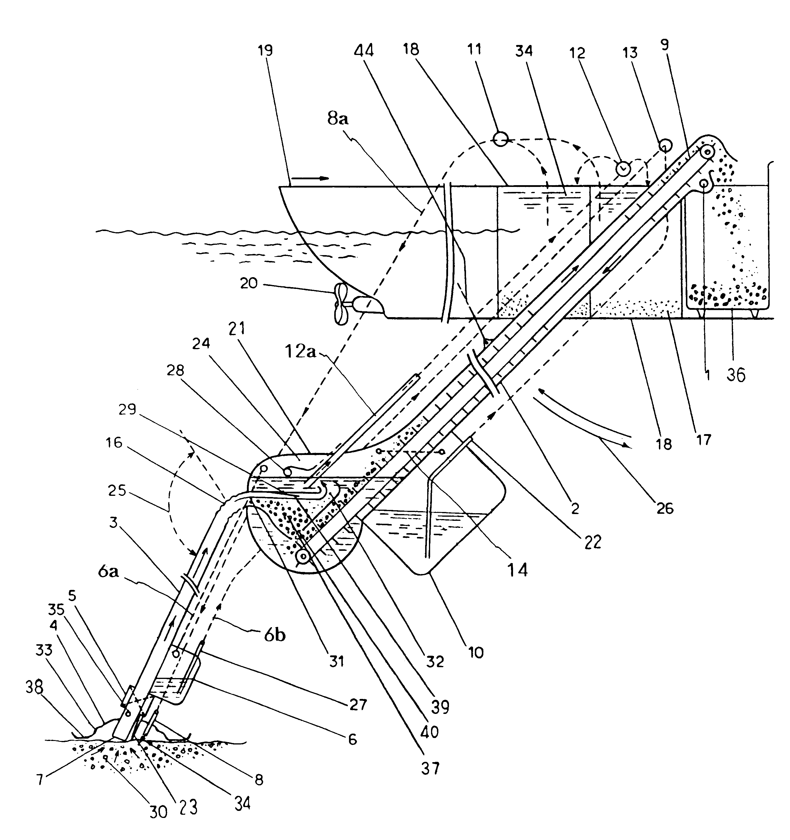
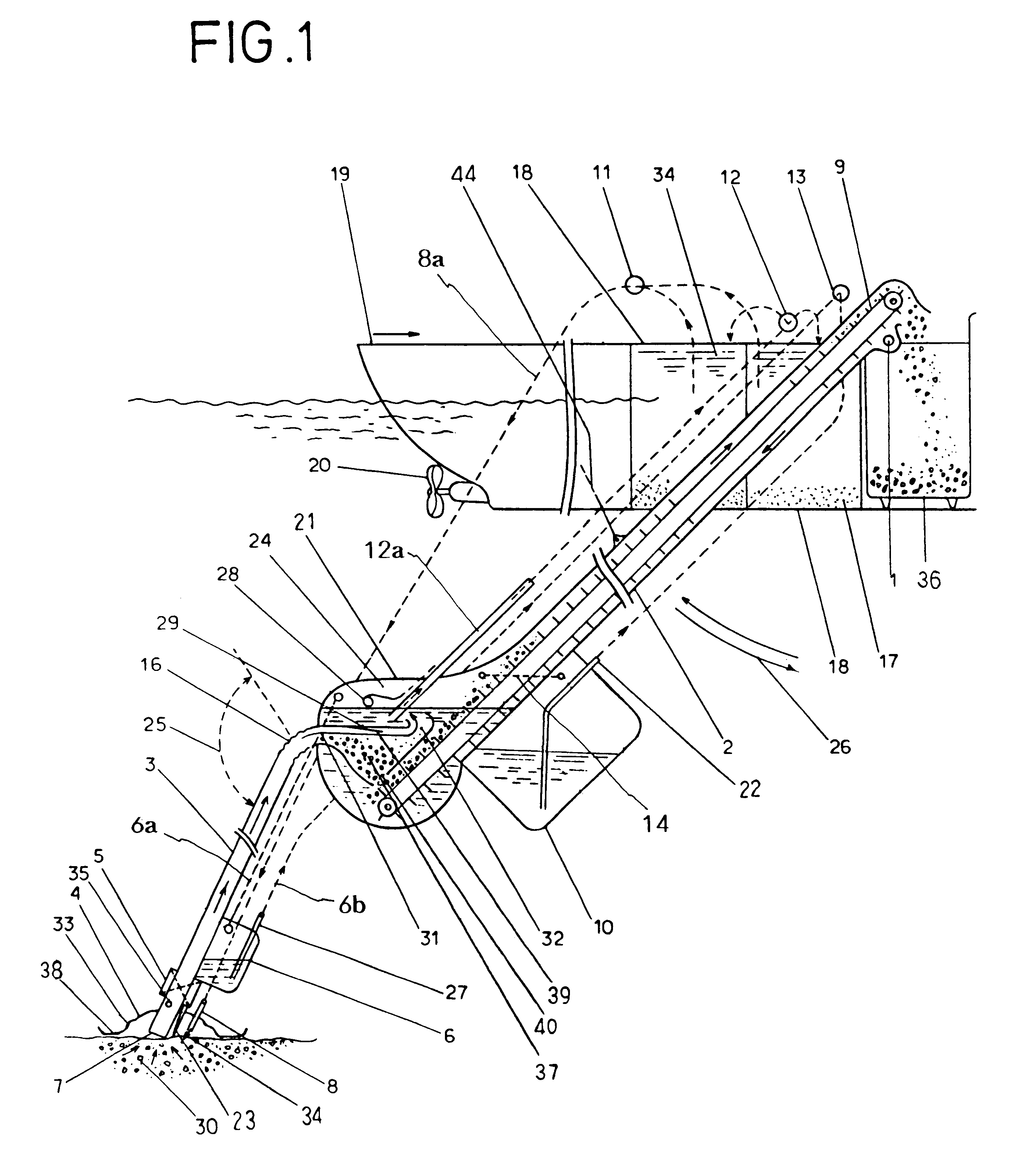
First Embodiment of the present invention is shown in FIGS. 1, 2 and 3.

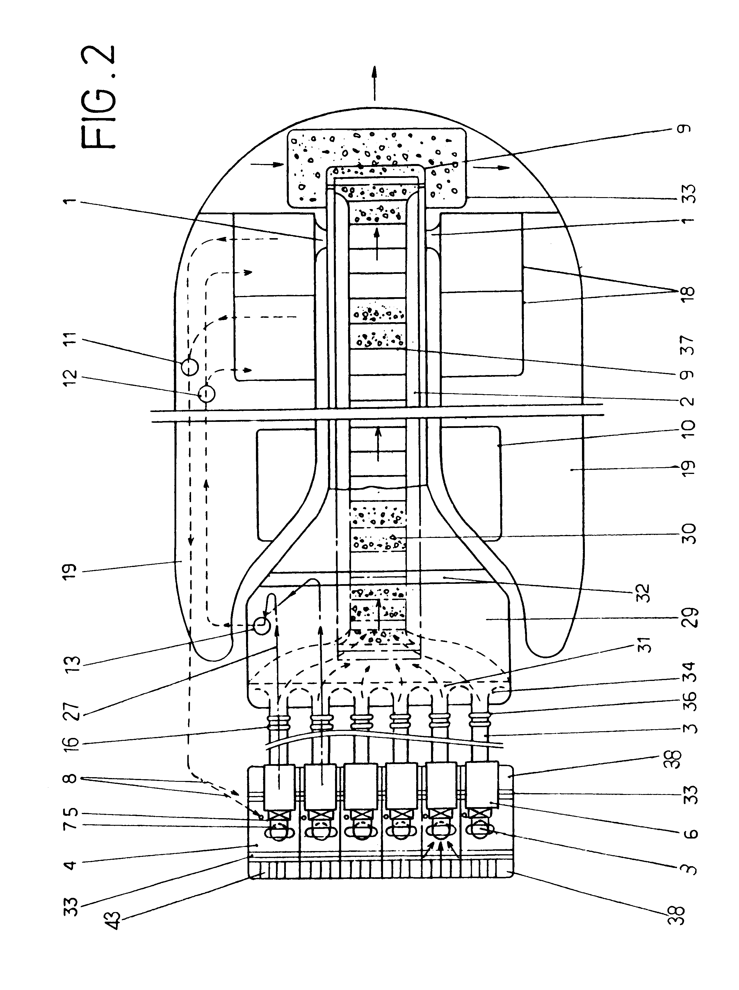
A symbol 19 stands for a dredging boat. As shown in FIG. 2, a planar shape of the dredging boat 19 is formed into a U-shape. Screws 20 are provided to each rear end of the boat 19, so that the boat 19 is capable of easily linearly moving and turning rightward and leftward.

A symbol 2 stands for a case, an upper part and a middle part thereof are formed into a cylindrical shape and its upper end is opened; a lower part thereof is formed into a pocket portion 21, whose sectional area is broader than that of the middle part, and its lower end is closed. The case 2 is located in an inner space of the U-shaped boat 19, and the upper end thereof is pivotably attached to the boat 19 by a horizontal shaft 1, so that the lower part can be (upwardly and downwardly) moved in the directions shown by arched arrows 26.

A symbol 9 stands for a conveyor for discharging sand and gravel, it is disposed in the case 2 and extended alo...

second embodiment

Second Embodiment will be explained with reference to FIGS. 4-8.

A symbol 101 stands for a dredging boat.

A symbol 102 stands for a case, which is downwardly extended from the boat 101 so as to sink a whole body thereof, except an upper end, into water.

An upper part of the case 102 is formed into a cylindrical shape, whose upper end is opened; a lower part thereof is formed into a pocket portion 102a, whose diameter is greater than that of the cylindrical upper part.

A symbol 109 stands for a container, which has a double wall structure, which is located under the boat 101 and in the water, and which is attached to the boat 101 by a holding member 109a. The holding member 109a and the container 109 are connected by proper fixing means, e.g., bolts.

An inner chamber of the container 109 is divided into a chamber "A" and a chamber "B" by a partition 109b. There is formed a connecting wall 109c along an open edge of the inner chamber.

A symbol 105 stands for a suction pipe, one end thereof ...


PUM


Abstract

A dredging method and a dredging apparatus which can efficiently suck large quantities of sand and gravels deposited on the bottom of dams, rivers, harbors, etc., convey them with as much saved energy as possible, and can prevent diffusion of turbid water. To achieve these objects, the apparatus includes a case laid down into the water in communication with the atmosphere. A suction pipe having a suction portion at the lower end thereof is connected to this case. The apparatus further includes a drain pump for draining water in the case and forming a level difference between the water level in the case and the external water level A container is removably disposed at an intermediate portion of the suction pipe. The sand and gravels are sucked from the suction pipe into the container by the siphon principle due to the level difference between the external water level and the water level in the container, and the container is cut off and the sand and gravels are taken out when the container is full.

Description

FIELD OF TECHNOLOGYThe present invention relates to a method of dredging and a dredging apparatus which can efficiently dredge large quantities of sand and gravels, deposited on the bottom of dams, rivers, harbours, etc.BACKGROUND TECHNOLOGYRecently, 80% or more of the capacities of some dams are filled with sand and gravels, thereby reducing dam operability and effectiveness.To recover their function, an effective dredging method and an effective dredging apparatus are required.Conventionally, sand and gravel deposites are removed by methods employing a dipper, a crab, a bucket, a pump or a siphon, which are selected according to the deposit condition of the sand and gravels.TECHNICAL PROBLEMSThe conventional dredging methods have the following problems.In the conventional methods not employing a siphon, a great power is required, so the dredging apparatus must be large and heavy. Further a large amount of turbid water, which is generated when the sand and gravels are dredged, rema...

Claims


Application Information

Patent Timeline
Patent Type & Authority Patents(United States)
IPC IPC(8): E02F3/88E02F3/90E02F3/92E02F7/00E02F7/02
CPCE02F3/88E02F3/8841E02F3/905E02F3/907E02F3/925E02F3/9256E02F7/005E02F7/023
Inventor OIKAWA, SENJI
Owner MOBURON DESIGN OFFICE
Why Eureka
Try Eureka