Ink-jet recording head

a recording head and inkjet technology, applied in printing and other directions, can solve the problems of large distance between common terminal electrodes, increased size of recording heads, and droplets of ink, and achieve the effect of preventing the variation of the electric potential of piezoelectric vibrators

Inactive Publication Date: 2001-02-20
SEIKO EPSON CORP
View PDF7 Cites 29 Cited by
  • Summary
  • Abstract
  • Description
  • Claims
  • Application Information

AI Technical Summary

Benefits of technology

An ink-jet recording head according to the present invention is provided with plural nozzle openings for jetting ink, a piezoelectric vibrator for expanding or reducing the volume of a pressure generating chamber communicating with a nozzle aperture, a segment terminal electrode provided corresponding to the above piezoelectric vibrator and connected to one pole of the piezoelectric vibrator and a common terminal electrode arranged at both ends in a direction in which the segment terminal electrodes are arranged and connected to the other pole of the piezoelectric vibrator, a tape carrier package having a segment terminal connected to the segment terminal electrode and having the relationship of continuity to a signal pattern for transmitting a driving signal generated based upon an input signal from an external device, a common terminal located at both ends of the segment terminal and connected to the common terminal electrode and a grounding conductor arranged on both sides and on the side of the input signal pattern and connected to the common terminal and a connecting member arranged at both ends of the segment terminal electrode for connecting the common terminal electrode. Owing to such constitution, the common terminal electrode formed at both ends of the actuator unit is securely connected to the grounding conductor in an area of the actuator unit and the electric potential of the piezoelectric vibrator can be prevented from varying.
Therefore, a first object of the ink-jet recording head according to the present invention is to provide an ink-jet recording head in which the electric potential of piezoelectric vibrators in plural rows is fixed possibly and an ink droplet can be stably jetted without increasing the size of the whole recording head.
A second object of the ink-jet recording head according to the present invention is to provide an ink-jet recording head in which TCP and a piezoelectric vibrator are prevented from coming in contact and an ink droplet can be stably jetted.

Problems solved by technology

As a result, the electric potential difference from the grounding conductor of each piezoelectric vibrator varies, the quantity in which the piezoelectric vibrator is displaced varies and there is a problem that as a result, the characteristic of jetting an ink droplet varies depending upon a nozzle aperture.
Therefore, there occurs a new problem that large distance is made between the common terminal electrode located at the other end for piezoelectric vibrators and the grounding conductor, the characteristic of displacement varies among piezoelectric vibrators in the same row and among piezoelectric vibrators in different rows and the characteristic of jetting an ink droplet varies.
To solve such problem, a method of increasing the area of the TCP and providing a grounding conductor outside is also conceivable, however, there is a problem that the size of the whole recording head is increased.
For a recording head using TCP in which a driving signal generating semiconductor integrated circuit is mounted on a flexible cable, there is a problem that as the rigidity of the flexible cable is increased, the characteristic related to oscillation of a piezoelectric vibrator varies due to deformation when TCP is connected to a recording head chip and contact between TCP and a piezoelectric vibrator and the characteristic of jetting ink is influenced.

Method used


Image

  • Ink-jet recording head
  • Ink-jet recording head
  • Ink-jet recording head

Examples


second embodiment

FIGS. 6 and 7 show the ink-jet recording head according to the present invention.

In a process for forming a piezoelectric vibrator 35 on a lower electrode 34 on the surface of an elastic plate 33 of an actuator unit 30, dummy piezoelectric vibrators 351 and 352 are respectively formed in the center and on both sides of the actuator unit 30.

In a process for forming an upper electrode 36 on the piezoelectric vibrator 35, the upper electrode 36 is formed on the dummy piezoelectric vibrator 351 on both sides of the actuator unit 30, a dummy upper electrode 361 not connected to the upper electrode 36 is formed on the dummy piezoelectric vibrator 352 in the center and further, segment terminal electrodes 381 and 382 connected to TCP 2 are formed on the surface of these upper electrodes 36 and 361.

first embodiment

According to this embodiment, the height from the elastic plate in an area in which the segment terminal electrodes 371 and 372 and the common electrode forming members 381 and 382 are formed can be made higher by the thickness of each dummy piezoelectric vibrator 351 and 352 than the height in an area in which the piezoelectric vibrator 35 is formed only by changing the shape of an electrode forming pattern and others without greatly changing the manufacturing process of the ink-jet recording head equivalent to the first embodiment, a gap g' between TCP 2 and the piezoelectric vibrator 35 is sufficiently secured and contact between TCP 2 and the piezoelectric vibrator 35 can be securely prevented.

third embodiment

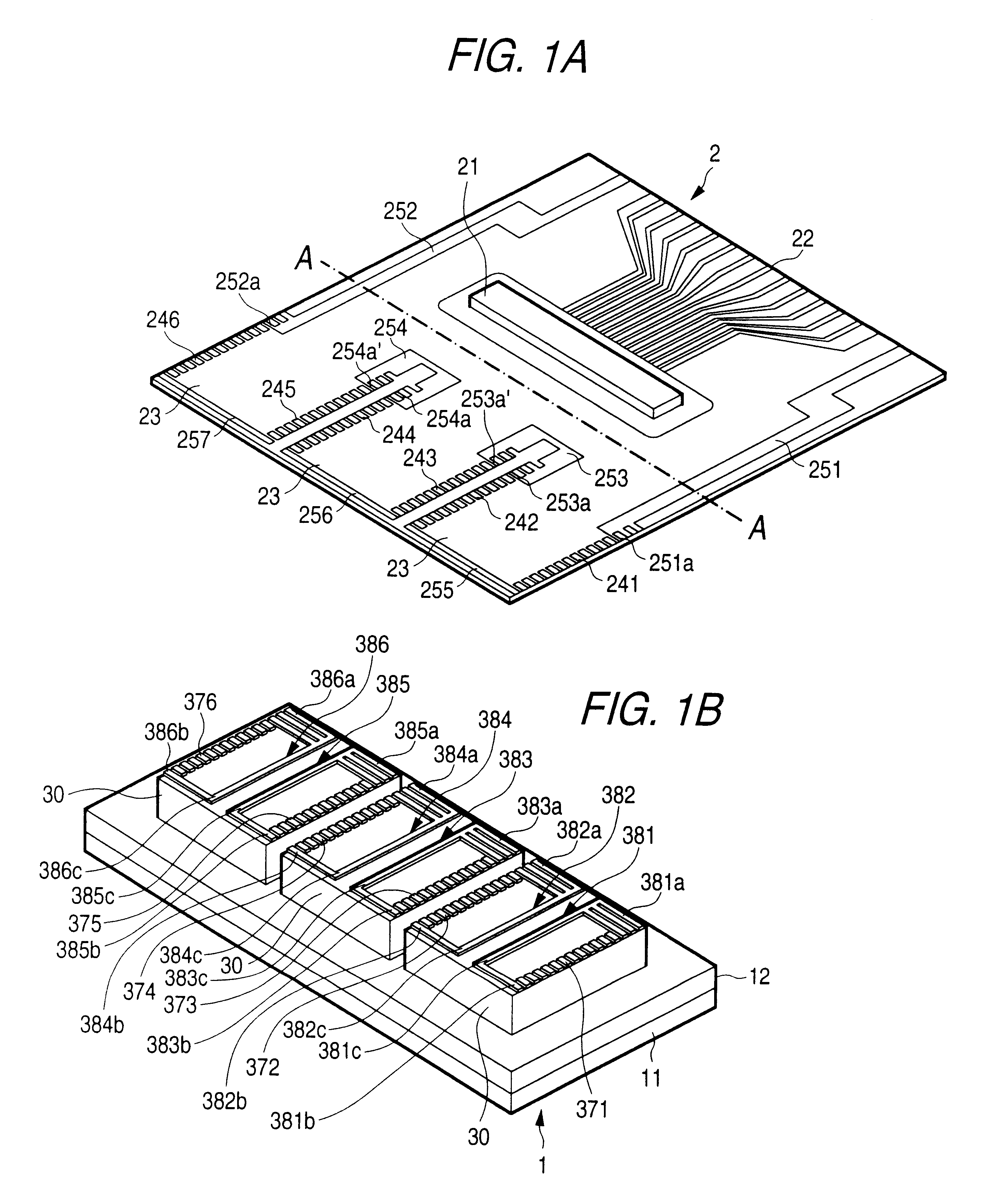
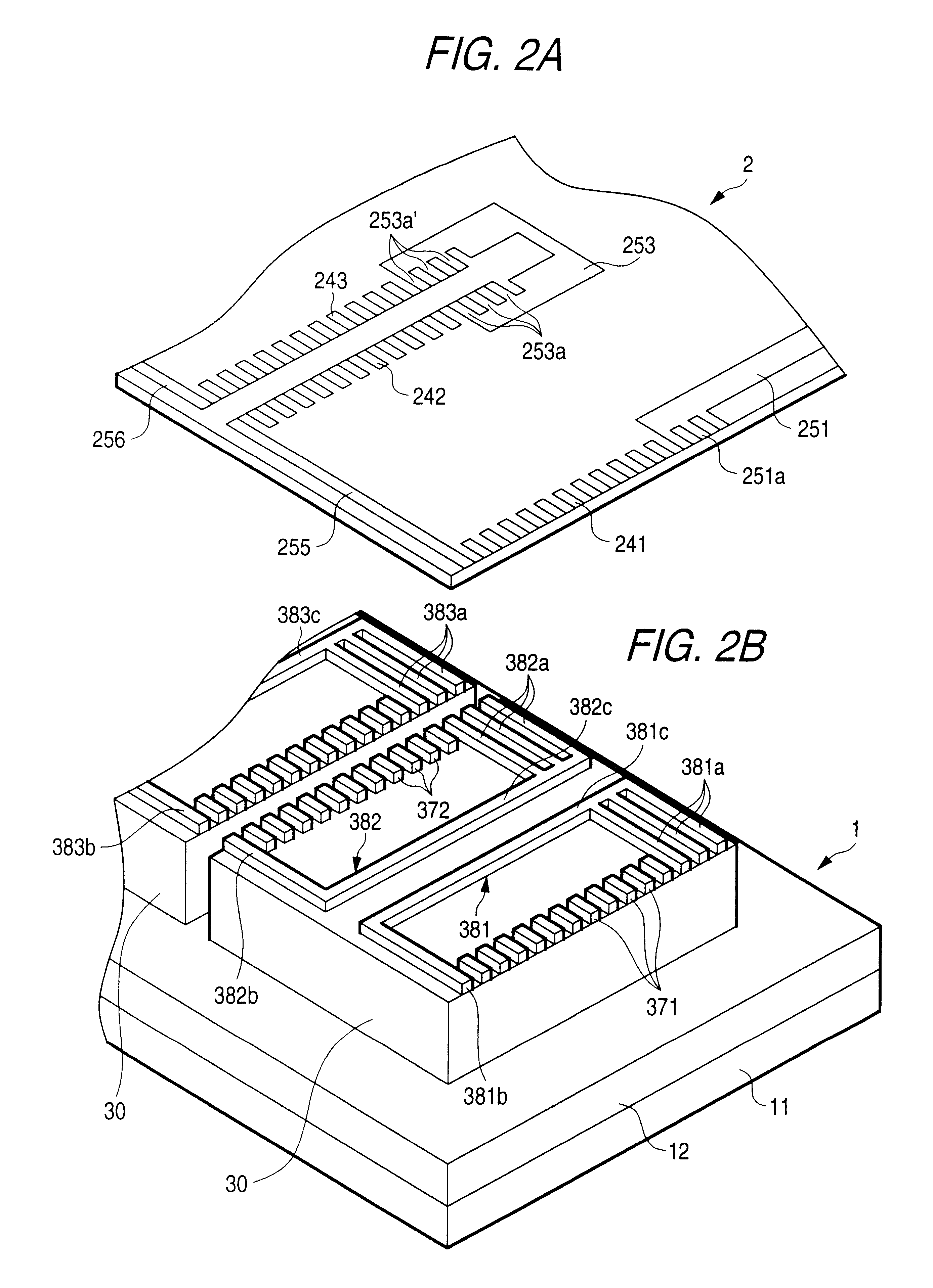
FIGS. 8 and 9 show the ink-jet recording head according to the present invention. In this embodiment, conductive members 381c to 386c for connecting the common terminal electrodes 381a, 381b to 386a, 386b arranged at both ends in a direction in which the segment terminal electrodes 371 to 376 are respectively arranged are not required and instead, the common terminal electrodes 381a, 381b to 386a, 386b arranged at both ends in a direction in which these segment terminal electrodes 371 to 376 are respectively arranged are connected via an external conductive member. An anisotropic conductive bonding film 6 is provided for connecting TCP 2 and a terminal which effects conductivity only in a pressurized direction and the above film is formed by mixing thermoplastic polymeric material and minute powder of metal and extending to be a film.

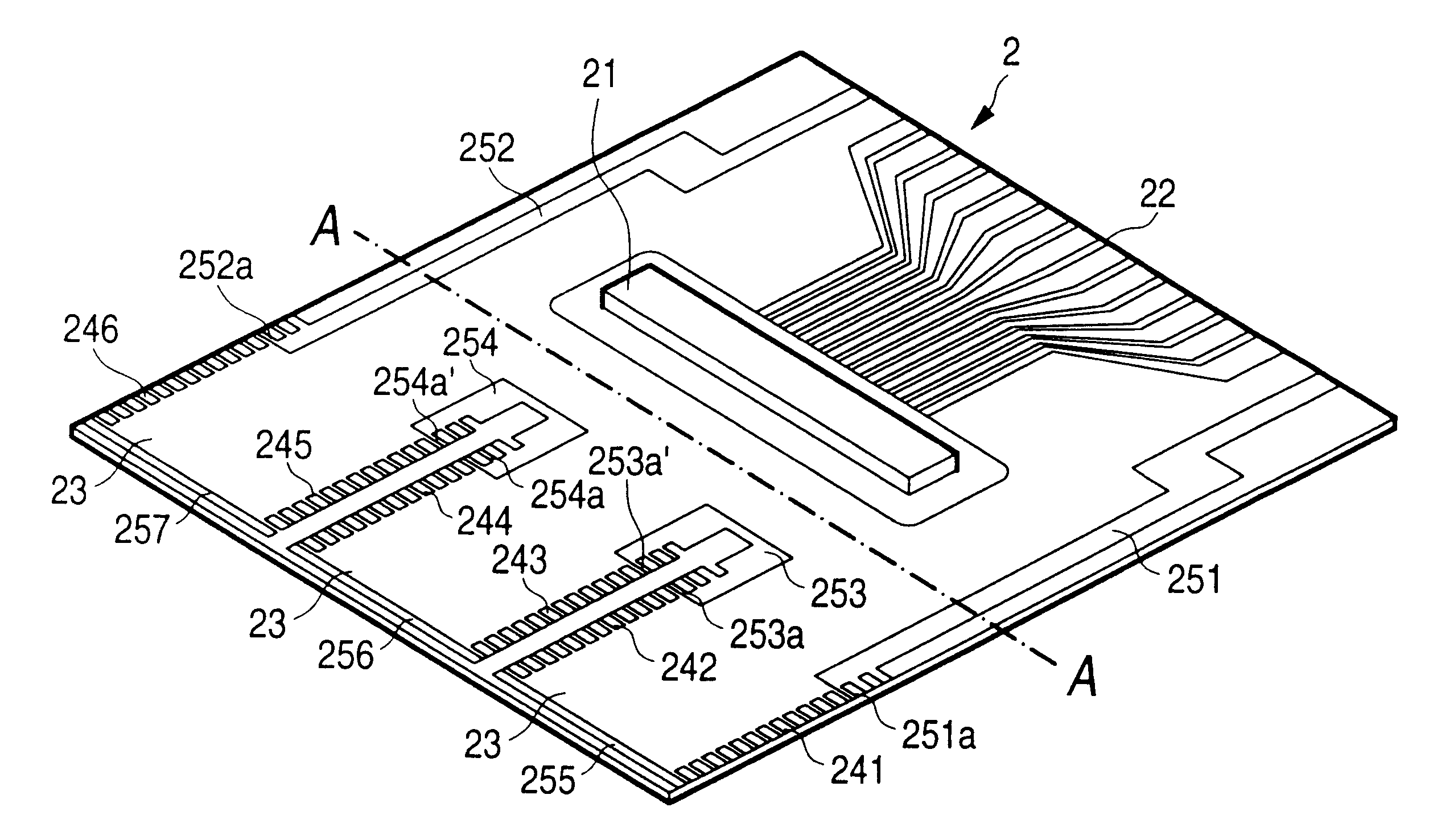
As shown in FIG. 10, TCP 2 in this embodiment is formed by mounting a semiconductor integrated circuit 21 for generating a driving signal on a flexible...


PUM


Abstract

Segment terminal electrodes for connecting to the segment terminals of TCP and common terminal electrodes at both ends in a direction in which these segment terminal electrodes are arranged are formed on the surface of an actuator unit and the common terminal electrodes at both ends of each row are connected via conductive members. Each grounding conductor on TCP is mutually connected via each common terminal electrode component on the actuator unit. Therefore, the common terminal electrodes on plural actuator units can conduct to grounding conductors.

Description

The present invention relates to an ink-jet recording head for jetting an ink droplet from a nozzle aperture by expanding and contracting the volume of a pressure generating chamber by a piezoelectric vibrator for flexural oscillation so as to print on recording medium. More specifically, the present invention relates to structure for connecting a piezoelectric vibrator and a cable.In an ink-jet recording head for jetting an ink droplet from a nozzle aperture by expanding and contracting the volume of a pressure generating chamber by a piezoelectric vibrator for flexural oscillation, a piezoelectric vibration plate is arranged on the surface of an elastic plate which is elastically deformable corresponding to each pressure generating chamber and a driving signal is applied to the piezoelectric vibration plate via a flexible cable.In such a flexible cable, signal lines of the same number as at least the number of piezoelectric vibrators and a common grounding conductor are normally f...

Claims


Application Information

Patent Timeline
Patent Type & Authority Patents(United States)
IPC IPC(8): B41J2/14
CPCB41J2/14233B41J2002/14362B41J2002/14491
Inventor KURASHIMA, NORIHIKOYONEKUBO, SHUJIOKUBO, KATSUHIRO
Owner SEIKO EPSON CORP
Why Eureka
Try Eureka