Resin molding apparatus and resin molding method

A technology of resin molding and resin, which is applied in the field of resin molding devices, and can solve problems such as increased device costs and complex device structures

Active Publication Date: 2015-10-28
TOWA
View PDF5 Cites 3 Cited by
  • Summary
  • Abstract
  • Description
  • Claims
  • Application Information

AI Technical Summary

Problems solved by technology

Therefore, in order to perform multi-chamber operation, the structure of the device becomes complicated, and the cost of the device also increases

Method used


Image

  • Resin molding apparatus and resin molding method
  • Resin molding apparatus and resin molding method
  • Resin molding apparatus and resin molding method

Examples


Embodiment 1

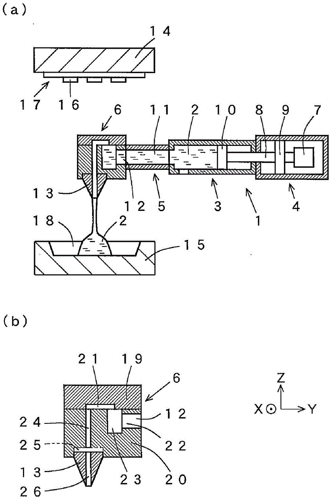
[0087] refer to figure 1 with figure 2 , Embodiment 1 of the resin supply mechanism of the resin molding apparatus according to the present invention will be described. For ease of understanding, any of the drawings in the present application documents are appropriately omitted or exaggerated to be schematically drawn. The same reference numerals are used for the same structural elements, and explanations are appropriately omitted.

[0088] figure 1 The dispenser 1 as a resin supply mechanism shown in (a) is a horizontal dispenser arrange|positioned along the horizontal direction. The dispenser 1 is provided with: a storage part 3 for storing the liquid resin 2; a metering and sending mechanism 4 for measuring and sending out the liquid resin 2 according to a predetermined amount; a resin transfer part 5 for transferring the sent out liquid resin 2; and a resin injection The mechanism 6 ejects the transferred liquid resin 2 .

[0089] The liquid resin 2 transferred from ...

Embodiment 2

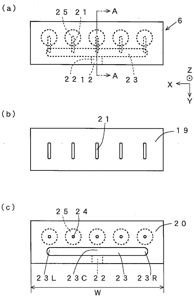
[0113] refer to image 3 , Embodiment 2 of the resin supply mechanism of the resin molding apparatus according to the present invention will be described. The difference from Example 1 is that the resin storage part 23 is formed as an annular groove in plan view. Other than that, it is the same as in Example 1, so description is omitted. Such as image 3 As shown in (c), the lower part 20 is provided with a resin passage 22, an annular resin storage part 23 connected to the resin passage 22 and formed in a horizontal plane (in a plane including the X-axis and Y-axis), along the vertical A plurality of thin resin passages 24 extending in the direction (-Z direction) are connected to the plurality of resin passages 24 and are used for installing nozzles 13 (refer to figure 1 (b)) a plurality of nozzle mounting ports 25. The annular resin storage portion 23 has resin storage portions 23a, 23b constituted by two extensions extending side by side. That is, it has a resin reser...

Embodiment 3

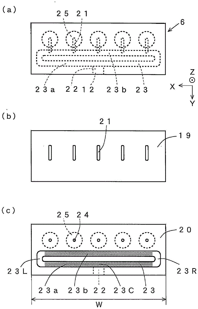
[0119] refer to Figure 4 , Embodiment 3 of the resin supply mechanism of the resin molding apparatus according to the present invention will be described. The difference from Embodiment 2 is that the central part of the resin storage part 23 a and the central part of the resin storage part 23 b are connected through the resin channel 27 in the annular resin storage part 23 . Other than that, it is the same as in Example 2.

[0120] Such as Figure 4 As shown in (c), the lower part 20 is provided with a resin passage 22, an annular resin storage part 23 connected to the resin passage 22, and a central part for connecting the resin storage part 23a and the central part of the resin storage part 23b. The resin passage 27 , the plurality of resin passages 24 extending in the vertical direction (−Z direction), and the plurality of nozzle mounting ports 25 connected to the plurality of resin passages 24 for mounting the nozzles 13 . In a state where the upper member 19 and the l...


PUM


Abstract

The invention provides a resin molding apparatus and a resin molding method. In the resin molding apparatus, liquid resin is equably injected at a specified amount from a plurality of nozzles. A resin injection mechanism (6) mounted at the front end of a distributor (1) comprises: a resin storage part (23) for storing the liquid resin (2); a plurality of resin channels (21), which are connected to the resin storage part (23) and extend along a horizontal direction; a plurality of resin channels (24) communicating with the resin channels (21) and extending along a vertical direction; and the plurality of nozzles (13) connected to the resin channels (24), respectively. The liquid resin (2) is supplied to and flows in the resin storage part (23), so that the liquid resin (2) can fill the resin storage part (23). The liquid resin (2) passes through the resin channels (21) extending along a horizontal direction from the top of the resin storage part (23), and through the resin channels (24) extending along a vertical direction from the resin channels (21) in sequence, and is injected towards each mold cavity (18) from the nozzles (13).

Description

technical field [0001] The present invention relates to a method for resin-encapsulating chip-shaped electronic components (hereinafter, appropriately referred to as "chips") such as transistors, integrated circuits (Integrated Circuit: IC) and light emitting diodes (Light Emitting Diode: LED) with liquid resin. Resin molding equipment and resin molding methods used in structures, etc. In this application document, the term "liquid" means that it is liquid at normal temperature and has fluidity, and does not relate to the level of fluidity, in other words, the degree of viscosity. Background technique [0002] Conventionally, a chip of an optical element such as an LED mounted on a substrate has been resin-encapsulated by using a thermosetting liquid resin that transmits light, such as silicone resin or epoxy resin, and an encapsulation resin made of cured resin. Resin encapsulation technology uses resin molding techniques such as compression molding and transfer molding. ...

Claims


Application Information

Patent Timeline
Patent Type & Authority Applications(China)
IPC IPC(8): B29C70/54B29C70/36
Inventor 藤原直己山田哲也后藤智行高田准子岩田康弘
Owner TOWA
Why Eureka
Try Eureka