
Electric motor

a technology of electric motors and motors, applied in the direction of rotating magnets, magnetic circuit rotating parts, synchronous machines with stationary armatures, etc., can solve the problems of weakened armature transverse field, reducing the efficiency of electric motors,

Inactive Publication Date: 2001-02-20
ROBERT BOSCH GMBH
View PDF6 Cites 34 Cited by
  • Summary
  • Abstract
  • Description
  • Claims
  • Application Information

AI Technical Summary

Benefits of technology

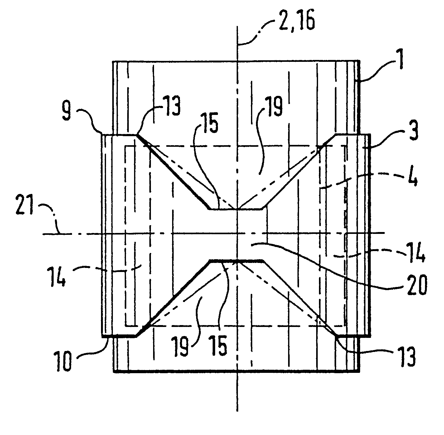
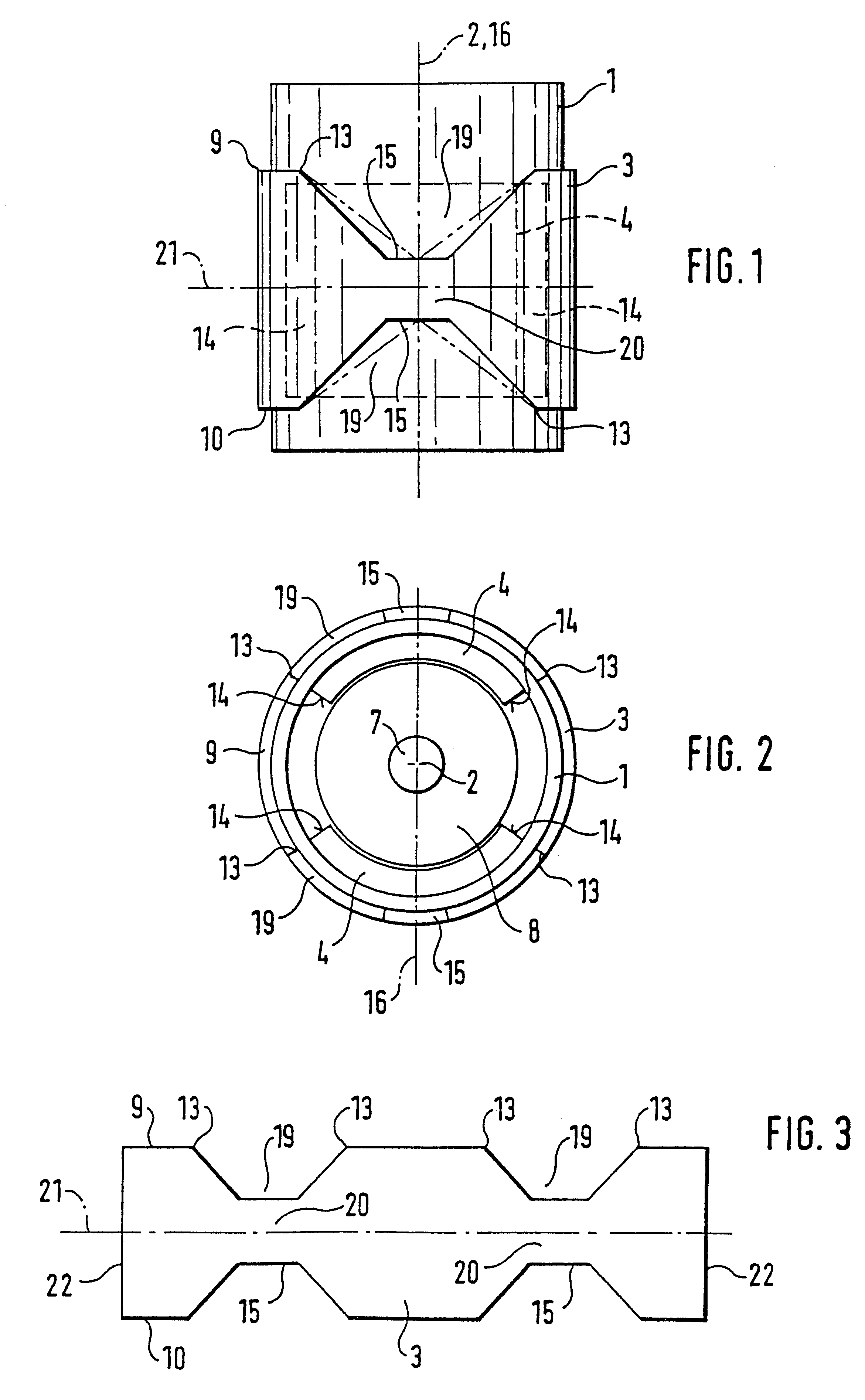
The electric motor according to the invention, has the advantage over the prior art that in addition to a reduction of the armature transverse field to improve the efficiency of the electric motor, the material quantity for the magnetic yoke is reduced, which reduces the weight of the electric motor and reduces the material costs. This advantage of the electric motor according to the invention is based on the knowledge that in order to conduct magnetic field lines in the vicinity of a symmetry plane of the permanent magnet segments extending through the longitudinal axis of the motor, a significantly smaller flux cross-section is required for the magnetic field lines than between the permanent magnet segments viewed in the circumference direction.

Problems solved by technology

The armature transverse field, which reduces the efficiency of the electric motor, is weakened by air gaps of this kind.

Method used


Image

  • Electric motor
  • Electric motor
  • Electric motor

Examples


Embodiment Construction

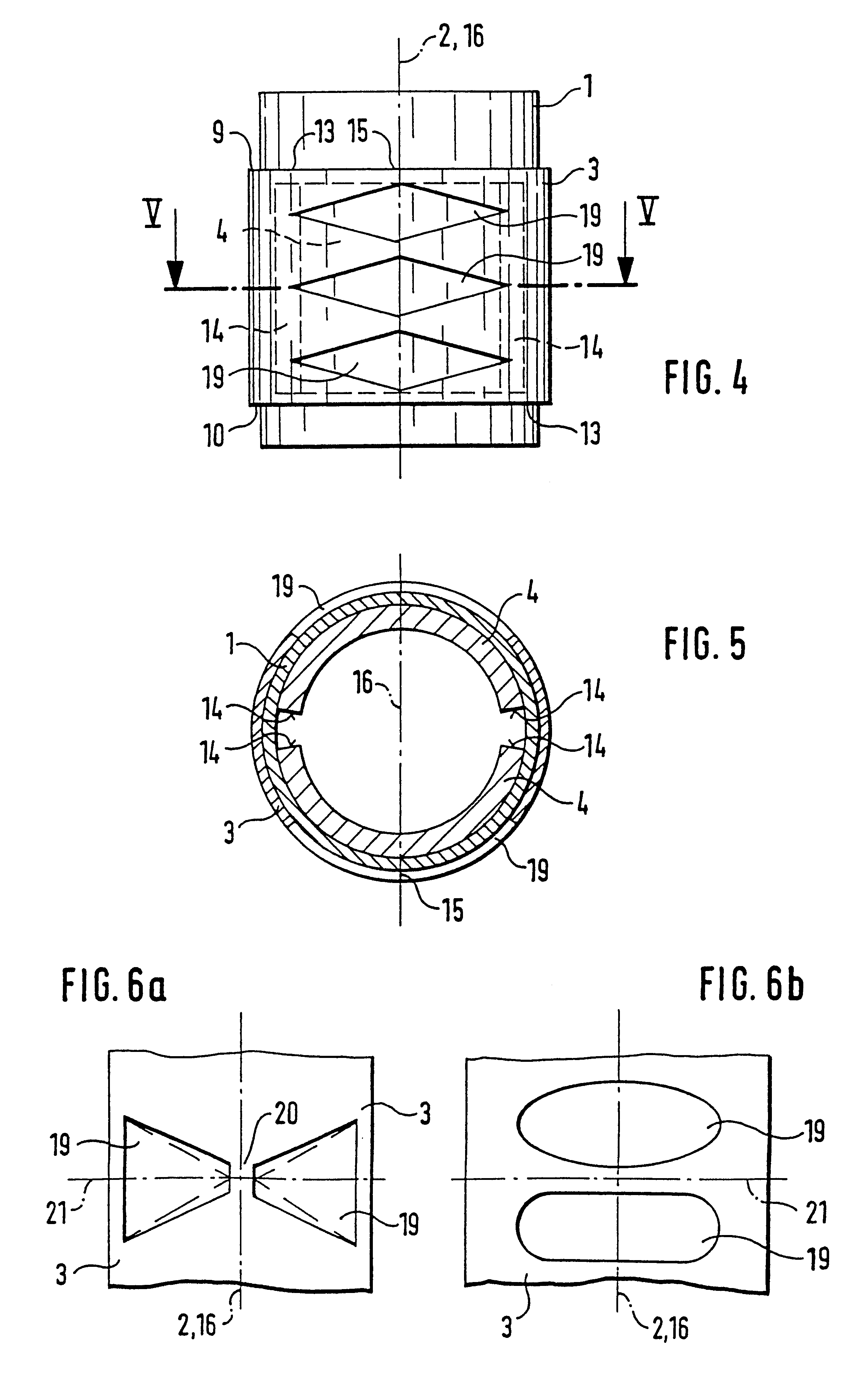
In FIG. 1, the numeral 1 is used to indicate a magnetically conductive pole housing of a d.c. motor excited by permanent magnets, which pole housing extends along a motor longitudinal axis 2 and, together with a magnetically conductive yoke ring 3 disposed on a pole housing 1, constitutes the magnetic yoke of the electric motor which is embodied as a d.c. motor. The yoke ring 3 is fixed securely and without an air gap onto the pole housing 1 and is either bent tightly around the cylindrical wall of the pole housing 1 as a sheet metal strip or is press-fitted onto the pole housing 1 as a closed ring. As can also be inferred from FIG. 2, the pole housing 1 supports at least two permanent magnet segments 4 against its inner wall, which, extending in a circular shape, partially encompass an armature 8, which is rotatably supported by means of a rotor shaft 7 and is only schematically indicated in the drawing, with circular, cylindrical pole surfaces. The armature 8 is provided with a nu...


PUM


Abstract

An electric motor, including at least two permanent magnet segments disposed around a motor longitudinal axis, in which each permanent magnet segment has end faces extending in the direction of the motor longitudinal axis and is encompassed by two independent yoke ring segments that have a gap between them parallel to a symmetry plane extending through the motor longitudinal axis and the center of the permanent magnet segments in order to reduce the armature transverse field. In addition to the reduction of the armature transverse field, a weight reduction of the electric motor is also achieved. To this end, in a first region close to the end faces of the permanent magnet segments, the one-piece magnetically conductive yoke is provided with a larger cross section than in a second region close to the symmetry plane extending through the center of the permanent magnet segments. The construction is particularly suited for small electric motors, in particular d.c. motors that are excited by permanent magnets.

Description

PRIOR ARTThe invention is based on an electric motor. An electric motor has already been disclosed (DE 26 37 705 A1) in which the magnetic yoke is comprised of two half shells which define an air gap between themselves, approximately in the middle of the permanent magnet segments. The armature transverse field, which reduces the efficiency of the electric motor, is weakened by air gaps of this kind.ADVANTAGES OF THE INVENTIONThe electric motor according to the invention, has the advantage over the prior art that in addition to a reduction of the armature transverse field to improve the efficiency of the electric motor, the material quantity for the magnetic yoke is reduced, which reduces the weight of the electric motor and reduces the material costs. This advantage of the electric motor according to the invention is based on the knowledge that in order to conduct magnetic field lines in the vicinity of a symmetry plane of the permanent magnet segments extending through the longitud...

Claims


Application Information

Patent Timeline
Patent Type & Authority Patents(United States)
IPC IPC(8): H02K1/12H02K1/17H02K23/02H02K23/04H02K1/27
CPCH02K1/17H02K23/04
Inventor FROEHLICH, PETERBRANDES, JOERGKOBSCHAETZKY, HANS
Owner ROBERT BOSCH GMBH
Learn More