Electrical terminal array with insulation displacement connectors and surge arrestors

a technology of terminal array and connector, which is applied in the direction of coupling device connection, basic electric elements, electrical apparatus, etc., can solve the problems of inhibiting the physical room available for the arrestor and inhibiting the dimensional requirements of the terminal, and achieves simple but effective electrical contact

Inactive Publication Date: 2001-02-27
A C AGERTON
View PDF16 Cites 55 Cited by
  • Summary
  • Abstract
  • Description
  • Claims
  • Application Information

AI Technical Summary

Benefits of technology

In a particularly preferred embodiment, the contact arms are non-unitary with the contact members but are joined thereto. This join can be by way of a lug extending from the edge of one of the two members and engaging within a slot of the other member. This provides a particul

Problems solved by technology

Difficulties arise in doing so in that the closely spaced nature of the electrical terminals inhibits the physical room available for the arrestor.
Fur

Method used


Image

  • Electrical terminal array with insulation displacement connectors and surge arrestors
  • Electrical terminal array with insulation displacement connectors and surge arrestors
  • Electrical terminal array with insulation displacement connectors and surge arrestors

Examples


Embodiment Construction

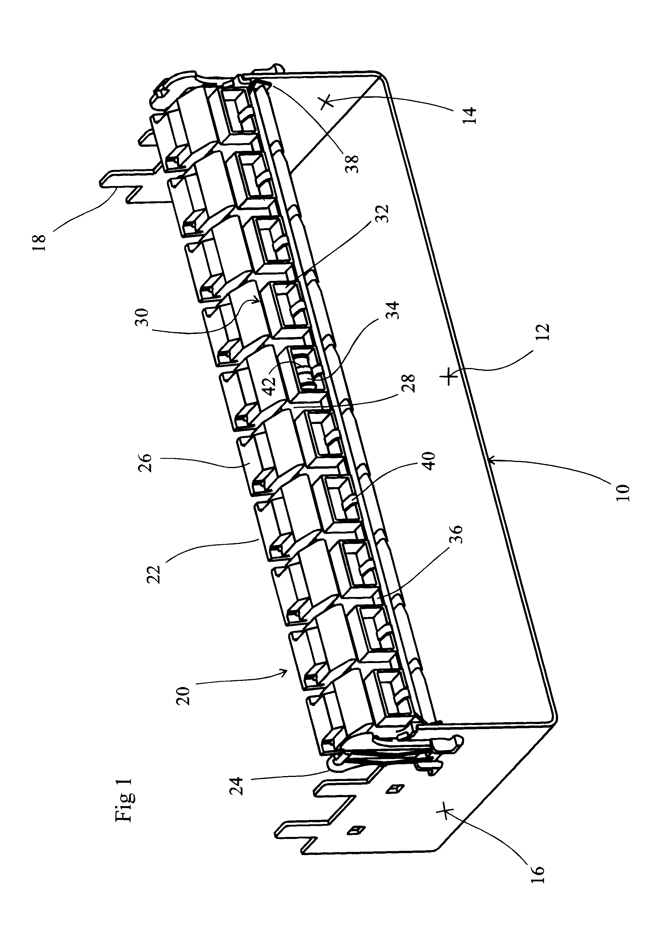
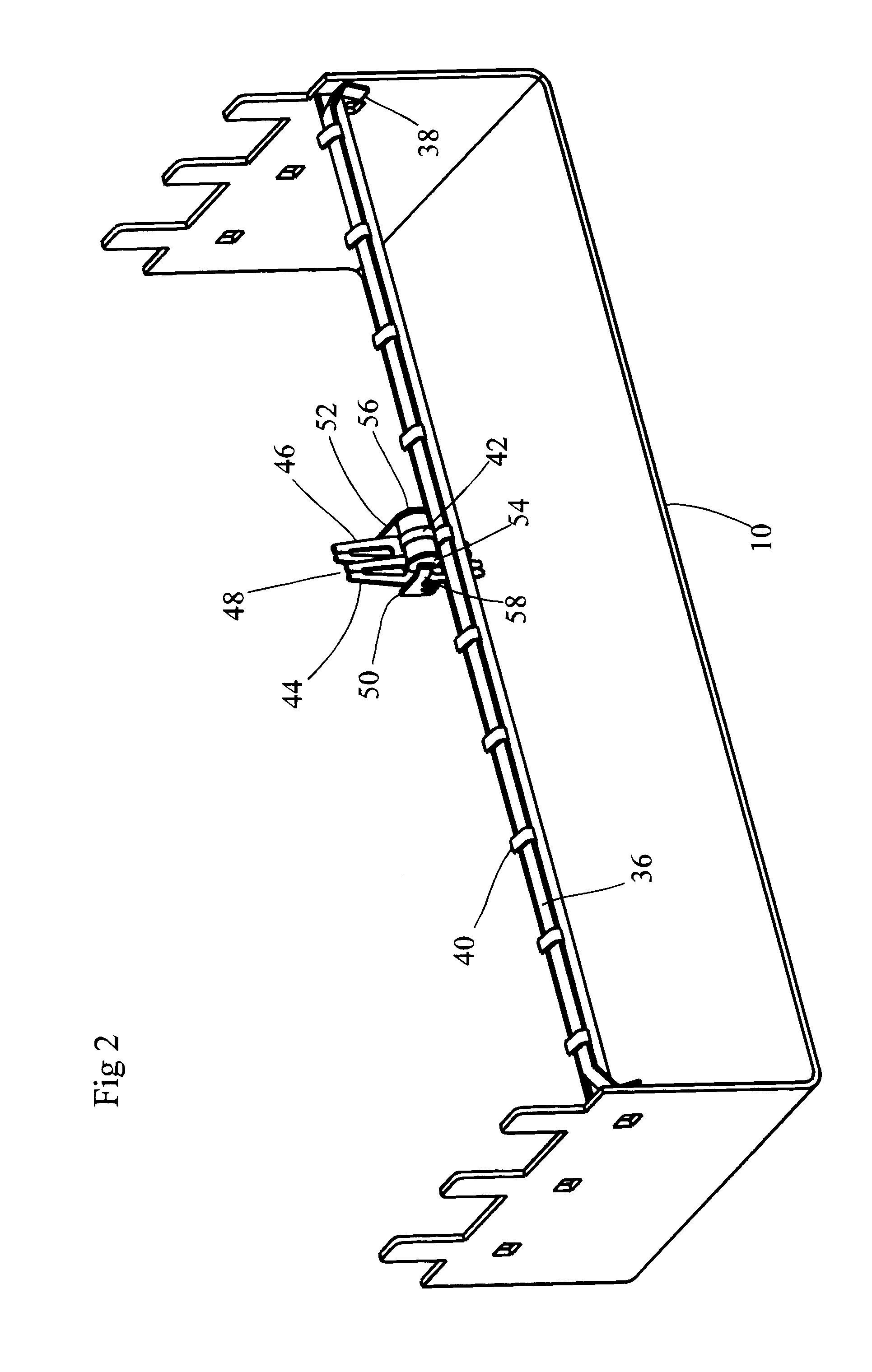
Referring to FIG. 1, this shows a metallic base unit 10 which comprises a floor portion 12 with upstanding parallel walls 14, 16 at either end thereof. Castellations such as shown at 18 extend upwardly from the upper edge of the walls 14, 16. The castellations 18 on the walls 14 and 16 are arranged so as to be in aligned pairs, one on each wall 14, 16. This permits a ten-connector array of terminals to be fitted onto each pair of castellations. Thus, a plurality of such arrays can be arranged in a generally parallel state to form a two dimensional array.

A single such array 20 of ten terminals 22 is shown in FIG. 1. This array 20 is held in place by clips 24 which fit over the castellations 18.

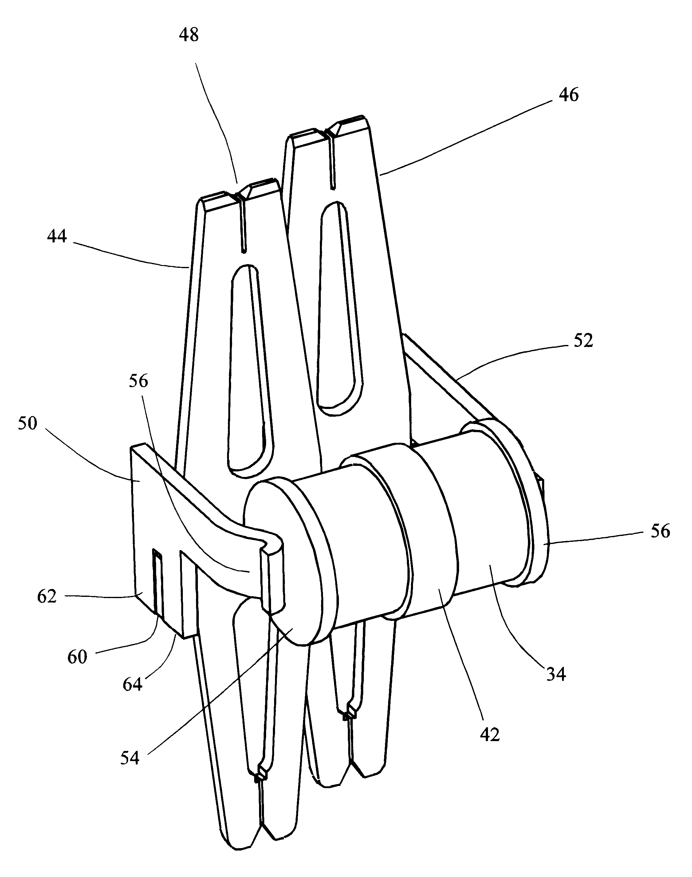
Each terminal 22 comprises a head portion 26 which is attached to a body portion 28 via a hinge line 30 at the rear of the terminal 22. Thus, the head portion 26 can move in a generally vertical direction. A pair of holes (not visible In FIG. 1) are formed on the front face of the head portion ...


PUM


Abstract

The application describes an electrical terminal comprising a pair of longitudinally disposed contact members, each having a pair of insulation displacement connectors connectors, one at either end thereof, thereby to link two wire pairs, wherein. each contact member comprises a contact arm each extending in a defined direction, the contact arms leading to a pair of arrestor contacts spaced so as to accept a surge arrestor. The defined direction is preferably substantially transverse to the contact members. This enables the surge arrestor to be placed to one side of the electrical terminal, avoiding interference with ingoing and outgoing wires and avoiding inhibiting access to test points. The contact members are preferably parallel within the electrical terminal. The arrestor contacts are preferably spring contacts, thereby to enable replacement of the arrestor. The contact arms more preferably end at the spring contacts. In a particularly preferred embodiment, the contact arms are non-contiguous with the contact members but are joined thereto. This join can be by way of a lug extending from the edge of one of the two members and engaging within a slot of the other. This provides a particularly simple but effective electrical contact. The lug is preferably on the contact members, thereby placing the slot on the contact arms. This also avoids the need to bend a single-piece blank, thereby risking damage to or distribution of the IDC connector. The terminal will ideally be enclosed within a plastic housing, and this will preferably comprise a recess for receiving the surge arrestor, the arrestor contacts extending into the recess.

Description

The present invention relates to an electrical terminal.DESCRIPTION OF BACKGROUND ARTIn the telecommunications field, it is necessary to create a large number of semi-permanent electrical connections between wire pairs. Such connections are usually made with releasable connectors such as shown in our earlier British Patent applications Nos. GB-A-2293699 and GB-A-2303500. The former shows the arrangement in which such connectors, sold by us under the Trade Mark "Mini Rocker" are arranged, i.e. in parallel strips of ten connectors. It is necessary to arrange the connectors in a compact array such that the entire apparatus does not occupy an excessive volume, in view of the large number of wire pairs to be connected.Telephone lines are often suspended above ground where they are susceptible to lightning strike. Lines are also at risk of contact with electrical power cables, whether above or below ground. This means that it is often necessary to provide surge protection for telecommunic...

Claims


Application Information

Patent Timeline
IPC IPC(8): H01R4/24H01R9/24
CPCH01R4/2429H01R9/2441Y10S439/922
Inventor ESCANE, RICHARD
Owner A C AGERTON
Why Eureka
Try Eureka