Device for suspension of a hollow section rail which opens downward in a suspension crane

a technology of hollow section rail and crane, which is applied in the direction of rope railways, runways, roads, etc., can solve the problems of short-term horizontal forces with very large amplitude, the suspension type of the above mentioned crane is not suitable for the crane, and the damage to the suspension path and ceiling construction

Inactive Publication Date: 2001-03-06
TEREX MHPS
View PDF6 Cites 18 Cited by
  • Summary
  • Abstract
  • Description
  • Claims
  • Application Information

AI Technical Summary

Problems solved by technology

The pendulum type suspension described above is not suitable for a suspension crane, especially with a laterally projecting boom, because upwardly directed vertical forces are not absorbed.
The rigid suspension has the disadvantage that pulse peaks occurring during shocks may destroy or damage the suspension path and ceiling construction because, in these cases, besides the forces that are favorably absorbed by the suspensi...

Method used


Image

  • Device for suspension of a hollow section rail which opens downward in a suspension crane
  • Device for suspension of a hollow section rail which opens downward in a suspension crane
  • Device for suspension of a hollow section rail which opens downward in a suspension crane

Examples


Embodiment Construction

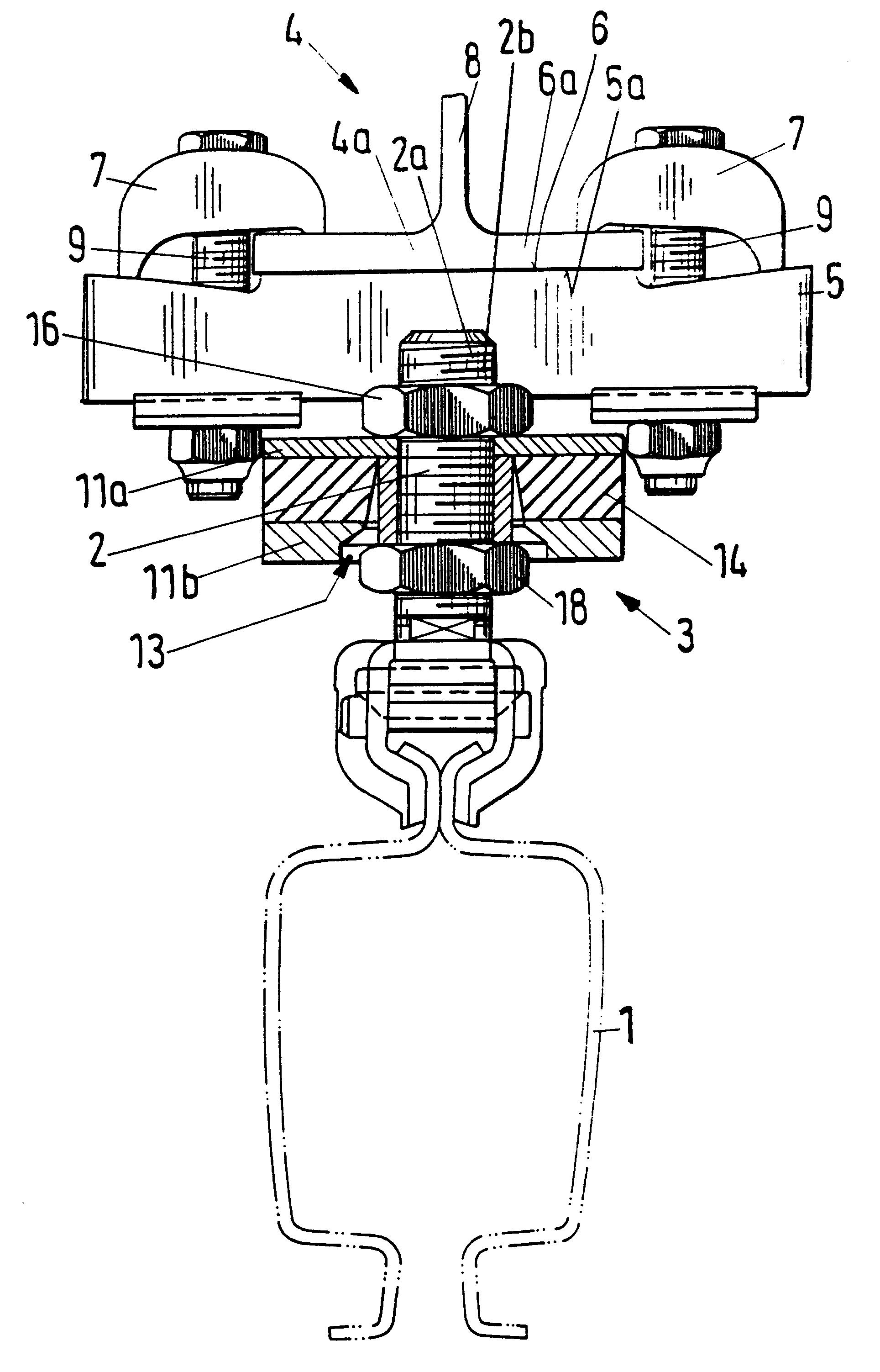
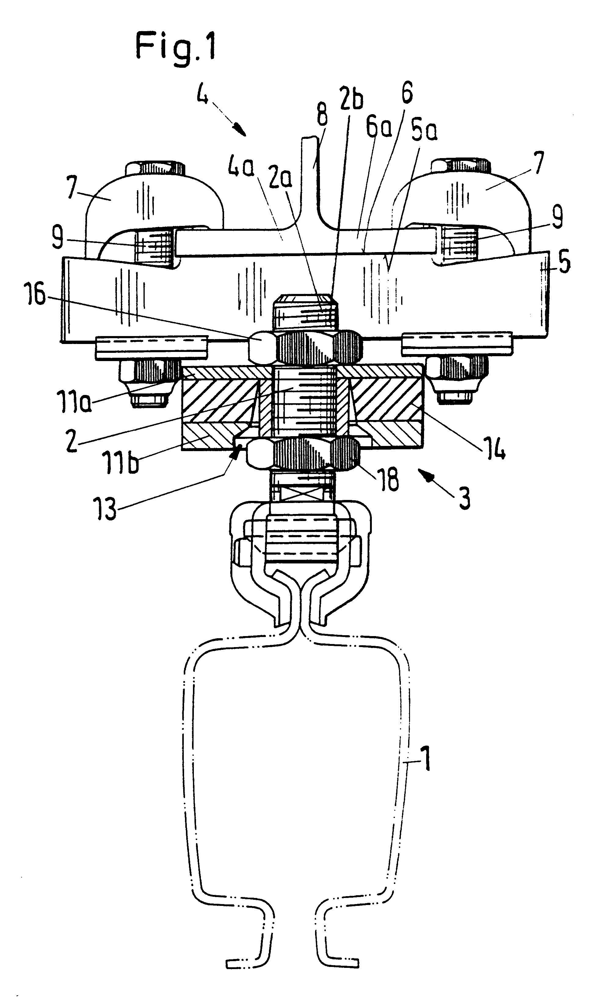
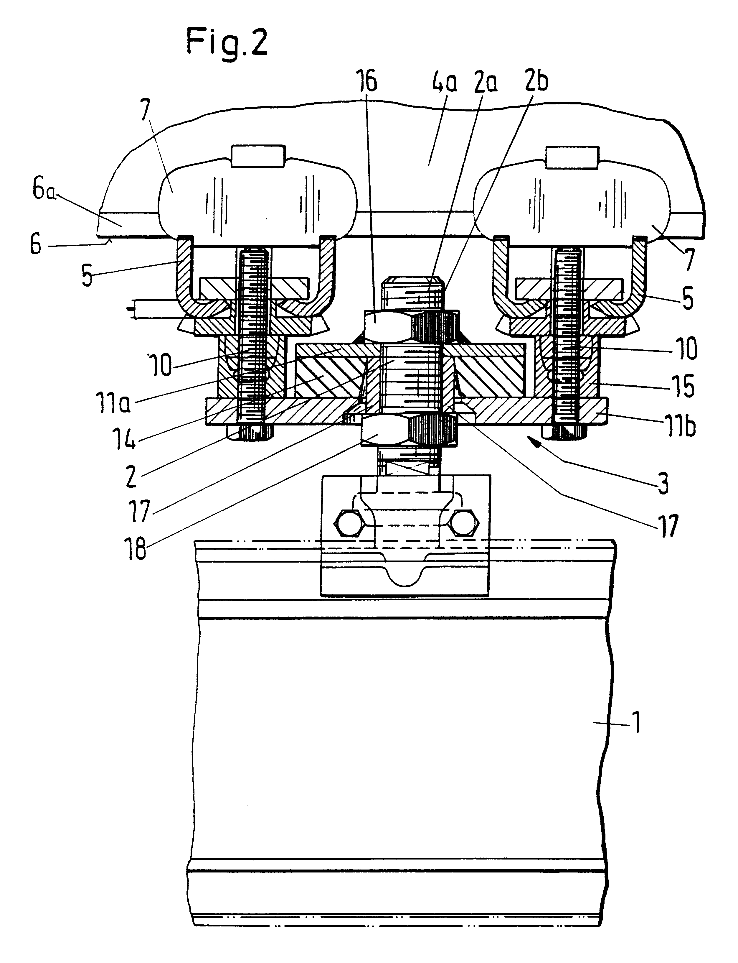
FIG. 1 and FIG. 2 show a device for the suspension of a hollow-section rail 1 for, by way of non-limiting example, a suspension crane, which opens downward. The rail 1 is connected to a carrying apparatus 4 by a traction element 2 via a rubber-metal element 3. The rubber-metal element 3 is an intermediate element connected between the carrying apparatus 4 and the traction element 2. The carrying apparatus 4 is constructed as a T-girder 4a in the embodiment shown in FIGS. 1 and 2 having a web 8 and a flange 6a. An upper edge 5a of a U-shaped transverse girder 5 which contacts a lower outer surface 6 of the T-girder 4a fastens the rubber-metal element 3 to the T-girder 4a. The fixed connection between the lower outer surface 6 and the transverse girder 5 is produced by brackets or plates 7 which are supported on both sides of the web 8 on the inner side of the flange 6a and on the transverse girder 5 extending beyond the width of the flange 6a. The plates 7 and the transverse girder 5...


PUM


Abstract

A device for the suspension of a rail, especially of a hollow-section rail which opens downward in a suspension crane, includes a carrying apparatus with a traction element which has two ends. One of the ends of the traction element may be fasten to the rail. To provide a rigid suspension of a rail in which horizontal forces, especially pulse-like horizontal forces, are extensively damped, the device includes a rubber-metal element connected between the carrying apparatus and the traction element with two substantially horizontal metal carriers arranged at a distance from one another. A rubber or elastic element is fastened to the inner surfaces of the metal carriers, which inner surfaces face one another. The carrying apparatus is fixedly connected with the lower metal carrier and the other end of the traction element is fixedly connected with the upper metal carrier.

Description

1. Field of the InventionThe invention is directed to a device for the suspension of a hollow-section rail in an overhead or suspension crane which opens downward.2. Description of the Related ArtA prior art hollow-section rail which opens downward for a suspended rail system is disclosed in the brochure titled "Kranbaukasten KBK (KBK Crane Construction Kits)", for a crane construction kit manufactured by Mannesmann Demag Fordertechnik AG. A lifting device is movable in the longitLudinal direction of the suspended rail system by trolley rails. The rail is suspended in pendulum fashion so as to be swivelable, at a carrying apparatus or a transverse girder by vertically arranged, elongate girders or traction elements, wherein the lower ends of the traction elements are fastened to the rail and the upper ends are fastened to the carrying apparatus or transverse girder. The pendulum type suspension ensures that the suspension path automatically adjusts to the state of equilibrium. The s...

Claims


Application Information

Patent Timeline
IPC IPC(8): B66C7/00B66C7/04
CPCB66C7/04
Inventor FITZLER, STEFANOSTHOLT, RUDIGER
Owner TEREX MHPS
Why Eureka
Try Eureka