Inductrack configuration

a technology of inductrack and configuration, applied in the direction of magnets, magnetic bearings, magnetic bodies, etc., can solve the problems of high-speed maglev trains based on these technologies, commercially operating rail systems, and technical complexity

Inactive Publication Date: 2005-09-22
LAWRENCE LIVERMORE NAT SECURITY LLC
View PDF10 Cites 28 Cited by
  • Summary
  • Abstract
  • Description
  • Claims
  • Application Information

AI Technical Summary

Benefits of technology

[0013] It is an object of the present invention to provide a simple permanent-magnet-excited maglev geometry that provides ...

Problems solved by technology

These decades-long efforts have resulted in impressive demonstration systems, but as yet have not led to commercially operating rail systems in these ...

Method used


Image

  • Inductrack configuration
  • Inductrack configuration
  • Inductrack configuration

Examples


Embodiment Construction

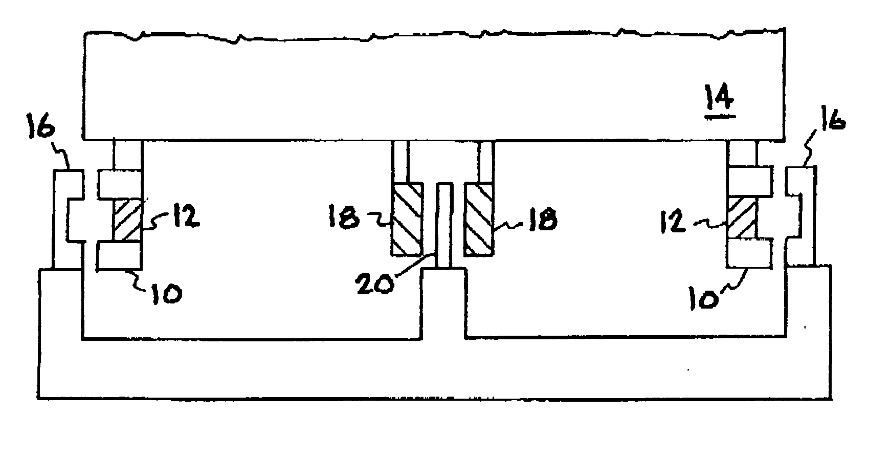
[0029] The present invention is an improved Inductrack configuration and represents a combination of the Inductrack principle of operation with another magnetic levitation configuration. The new combination represents an improvement in certain properties that is not achievable by either of the two configurations taken alone. The general Inductrack principle employed in some embodiments of this new idea is covered in U.S. Pat. No. 5,722,326, “Magnetic Levitation System for Moving Objects,” R. F. Post, incorporated herein by reference.

[0030] Other embodiments of the present invention employ the Inductrack II magnet configuration described in a copending U.S. patent application titled, “Improved Inductrack Magnet Configuration” filed on the same day as the present application and incorporated herein by reference. The magnet configuration of the above incorporated patent application is referred to sometimes herein as “Inductrack II”, wherein dual arrays are used, one on each side of tr...


PUM


Abstract

A simple permanent-magnet-excited maglev geometry provides levitation forces and is stable against vertical displacements from equilibrium but is unstable against horizontal displacements. An Inductrack system is then used in conjunction with this system to effect stabilization against horizontal displacements and to provide centering forces to overcome centrifugal forces when the vehicle is traversing curved sections of a track or when any other transient horizontal force is present. In some proposed embodiments, the Inductrack track elements are also employed as the stator of a linear induction-motor drive and braking system.

Description

[0001] This is a Divisional of U.S. patent application Ser. No. 09 / 896,579, titled “Improved Inductrack Configuration,” filed Jun. 29, 2001 and incorporated herein by reference.[0002] The United States Government has rights in this invention pursuant to Contract No. W-7405-ENG-48 between the United States Departnent of Energy and the University of California for the operation of Lawrence Livermore National Laboratory.BACKGROUND OF THE INVENTION [0003] 1. Field of the Invention [0004] The present invention relates generally to magnetic levitation systems for moving objects, and more specifically, to an improved magnetic levitation train system. [0005] 2. Description of Related Art [0006] Halbach arrays, invented by Klaus Halbach in the 1980s for use in particle accelerators, represent a maximally efficient way to arrange permanent-magnet material when it is desired to produce a strong periodic magnetic field adjacent to the array. The beauty of the concept is that the effect of the c...

Claims


Application Information

Patent Timeline
IPC IPC(8): B60L13/04
CPCB60L13/04B60L2200/26F16C32/0406F16C39/063F16C29/00F16C2326/10
Inventor POST, RICHARD FREEMAN
Owner LAWRENCE LIVERMORE NAT SECURITY LLC
Why Eureka
Try Eureka