
Polarizing system for motion visual depth effects

a technology of motion visual depth and polarizing system, which is applied in the direction of photographic printing, instruments, printers, etc., can solve the problems of affecting the effect of polarizing system, undesirable side effects, and eye receiving less light,

Inactive Publication Date: 2001-03-06
EVERGREEN INNOVATIONS L L C
View PDF11 Cites 38 Cited by
  • Summary
  • Abstract
  • Description
  • Claims
  • Application Information

AI Technical Summary

Benefits of technology

The present invention relates to methods and apparatus for using polarizing lenses to make scenes containing laterally moving objects appear brighter to either the left eye or the right eye to produce bi-directional visual depth effects.
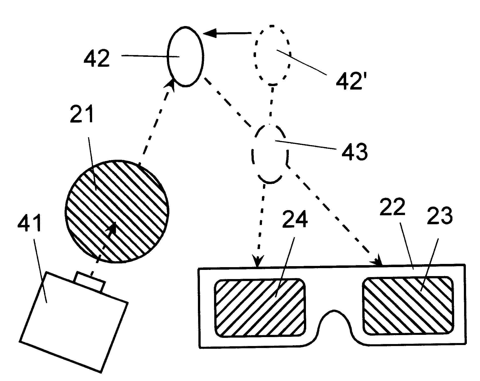
FIG. 8 shows the visual depth effect for an observer viewing a scene illuminated by light projected through a polarizing projection filter with the plane of polarization rotated counterclockwise from horizontal. The object in the scene is moving from right to left.

Problems solved by technology

The apparatus used to produce the standard Pulfrich Effect tends to cause an undesirable side effect.
This produces the sensation that the eye receiving less light is not working or dead.
This dead eye effect becomes irritating to observers over time.
It also restricts the use of colors in imagery.
They are all also somewhat prone to the dead eye effect.
This limits the choice of colors in the imagery.
This can reduce the strength of the perceived depth effects.
The projection screens of certain movie theaters cause partial depolarization of the light of the projected imagery.
This can reduce the strength of the perceived depth effects for U.S. Pat. No. 5,751,397 when these projection screens are used.

Method used


Image

  • Polarizing system for motion visual depth effects
  • Polarizing system for motion visual depth effects
  • Polarizing system for motion visual depth effects

Examples


first embodiment -

First Embodiment--Viewing Screen Preserves Imagery Polarization

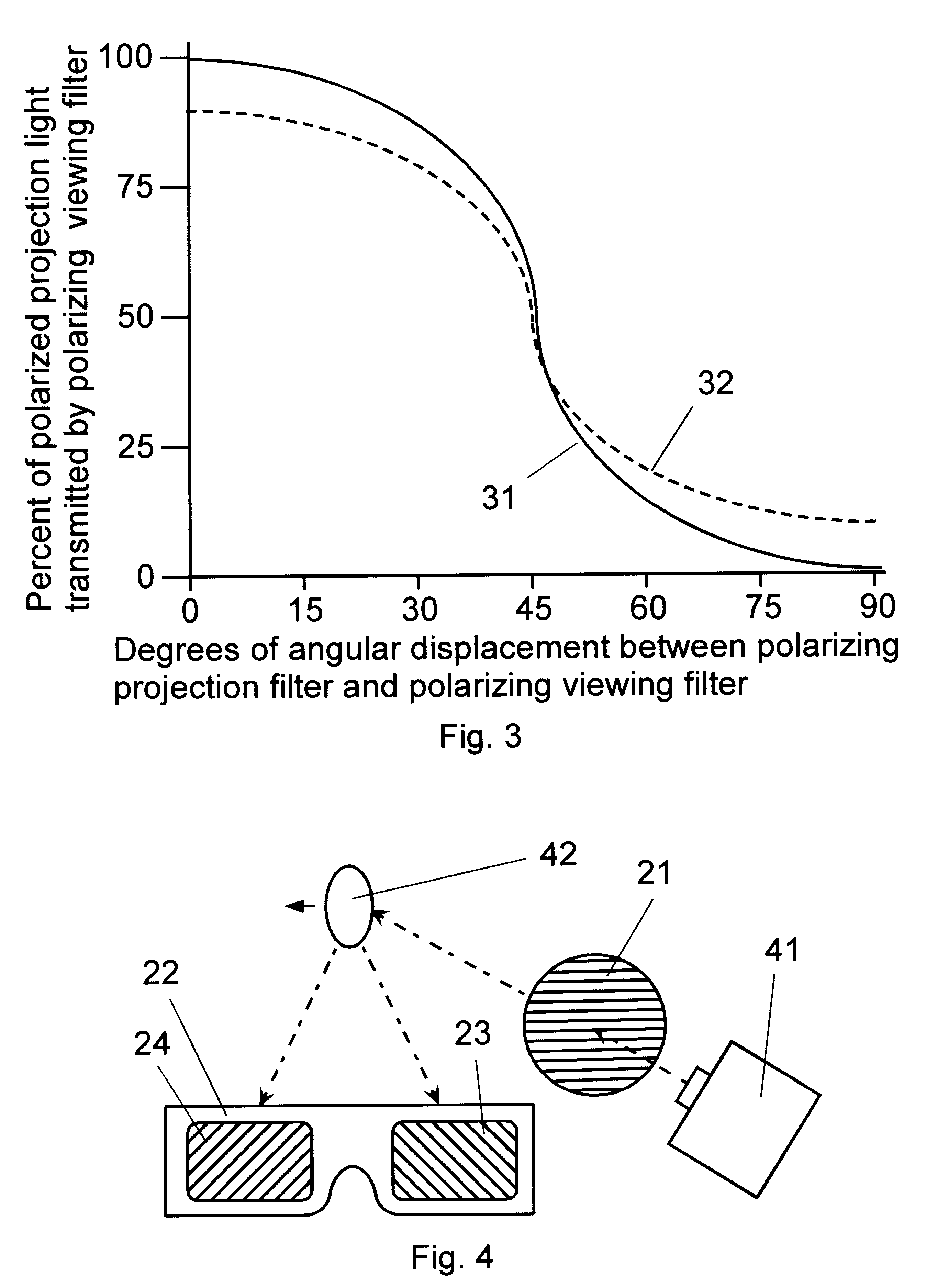
In a first embodiment of the present invention the scene is produced by projected imagery. The imagery is projected through the projection filter onto a viewing screen that preserves the polarization of the projected imagery. FIG. 4 shows a projector 41; a polarizing projection filter 21 with the plane of polarization oriented horizontally; viewing glasses 22 with a polarizing viewing filter for the right eye 23 with the plane of polarization rotated 45 degrees clockwise from horizontal, and a polarizing viewing filter for the left eye 24 with the plane of polarization rotated 45 degrees counterclockwise from horizontal; and a laterally moving object 42. The light projector 41 may be a movie or video projector that projects imagery onto a screen. The polarizing viewing glasses 22 and the laterally moving object 42 are shown from the observer's perspective. Light from the projector 41 is projected through the polarizing p...

second embodiment -

Second Embodiment--Viewing Screen Partially Depolarizes Imagery

second embodiment

the invention is similar to the first embodiment. The viewing screen of the second embodiment partially depolarizes the light of the projected imagery in a random manner. The angle of rotation of the projection polarizing filter is increased for the second embodiment to compensate for the depolarization of the projected light by the projection screen. FIG. 5 shows a visual depth effect for the second embodiment produced when the polarizing plane of the projection filter 21 is rotated approximately 45 degrees clockwise from horizontal. The light from the projector 41 which is transmitted by the polarizing projection filter 21 is polarized in a plane rotated 45 degrees clockwise from horizontal. If the viewing screen depolarizes approximately 10% of the reflected light, approximately 95% of the reflected light is transmitted by the polarizing viewing filter for the right eye. Approximately 5% of the reflected light is transmitted by the polarizing viewing filter for the left eye. When...


PUM


Abstract

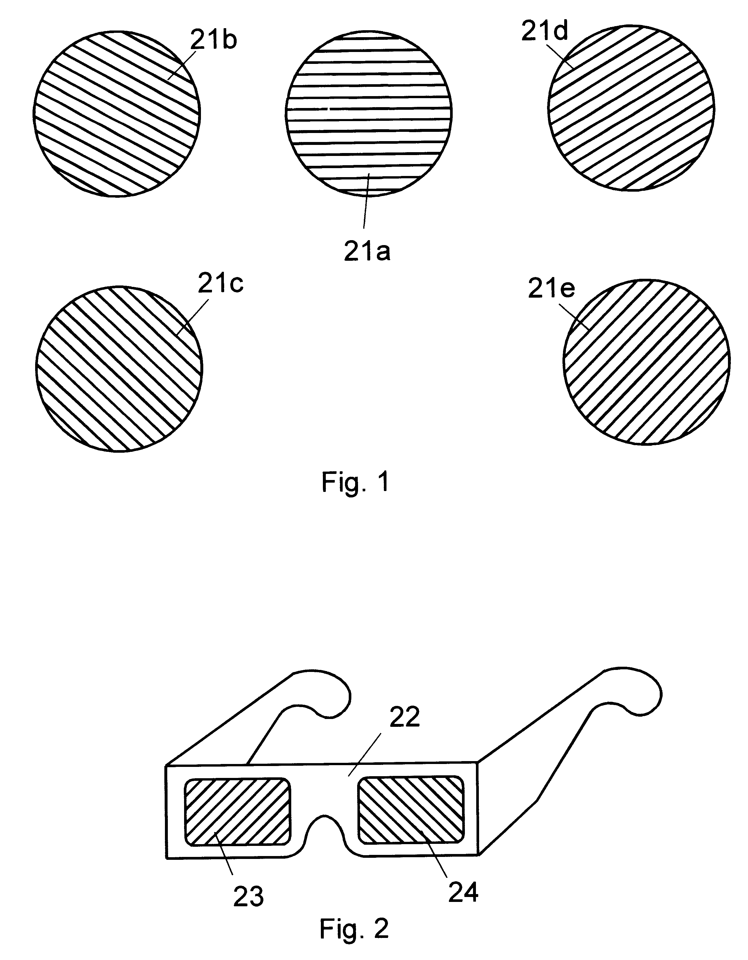
A system for creating the perception of visual depth in scenery comprising lateral movements. A polarizing projection filter 21 controls the plane of polarization of projected light. The plane of polarization is changed by changing the orientation of the polarizing projection filter. An observer wears special viewing glasses 22 with polarizing filters when viewing scenery illuminated by the polarizing projection filter. The plane of polarization of the polarizing viewing filter for the right eye 23 is rotated 45 degrees clockwise from horizontal. The plane of polarization of the polarizing viewing filter for the left eye 24 is rotated 45 degrees counterclockwise from horizontal. When the polarizing projection filter is rotated clockwise from horizontal the scenery appears brighter to an observer's right eye than to the observer's left eye. Objects moving laterally 42 from right to left from the observer's perspective appear closer to the observer 43. Objects moving from left to right appear farther away from the observer. When the polarizing projection filter is rotated counterclockwise from horizontal the scenery appears brighter to an observer's left eye than to the observer's right eye. Objects moving from right to left from the observer's perspective appear farther away from the observer. Objects moving from left to right appear closer to the observer. In the first and second embodiment of the invention, the scenery comprises polarized imagery projected on a viewing screen. In the third embodiment, the scenery comprises live scenes illuminated by polarized light. The scenery can be viewed in full color. The dead eye effect can be avoided by periodically changing the plane of polarization of the polarizing projection filter.

Description

1. The Field of the InventionThe present invention relates to methods and apparatus for using polarizing lenses or filters to create the perception of visual depth when viewing laterally moving objects in two dimensional single image displays and live scenes. In a further aspect, the present invention relates to the plane of polarization of polarizing filters used to produce the visual depth effects. In a still further aspect, the present invention relates to methods of controlling the movement of objects to create visual depth effects when observers wear glasses with polarizing lenses. The system is suited for motion picture films. The methods and apparatus may also be used for live scenes such as stage productions, video displays (television, computer displays, video games, etc.) and other types of media.2. The Prior ArtThe prior art includes methods to create the perception of depth in two-dimensional motion picture films and video displays. These methods have been described in o...

Claims


Application Information

Patent Timeline
IPC IPC(8): G02B27/26G03B35/26G03B35/18G02B27/22H04N13/00G02B30/25
CPCG02B27/26G03B35/26H04N13/0434H04N13/0459G02B30/25H04N13/337H04N13/363
Inventor OSGOOD, ALAN GEORGE
Owner EVERGREEN INNOVATIONS L L C
Learn More